The Netduino forums have been replaced by new forums at community.wildernesslabs.co.
This site has been preserved for archival purposes only
and the ability to make new accounts or posts has been turned off.
What's this?
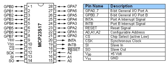
This thread is about a software driver for a chip called MCP23S17 that provides 16 additional digital IO pins to a micro controller such as the one on your Netduino.
The MCP23S17 gives you 16 digital input, output and interrupt enabled pins over SPI. Up to eight chips can be combined on a single SPI bus to provide a maximum of 128 pins.
Background
I was originally looking to make a dual ] board (Arduino shield form factor) for this driver to be used with. As so often however, I haven't found the time to complete the board so I decided to release the driver code for others to use.
About the software
The driver class is actually quite powerful and has a lot of features. The whole interface somewhat mimics that of native Netduino GPIOs in how they are created and used. Full source code is attached to this post.
You can create individual pins (input, output, interrupt) and also buses to represent a collection of pins in parallell.
The buses are very powerful - for example, you can easily create a 4 pin bus to be used in controlling an LCD or something like that.
You can also read and write pins or buses in a so called "burst mode" - this will result in bit streams in either direction at about a tenth of the configured SPI speed.
The driver can also be used in a special "direct mode" where all the built-in code for thread safe pin management etc is bypassed in favor of more speed.
How to use it
Simply download the attached code file and add it to your project and start coding with it - these lines of code the only ones needed for an output port:
// create driver to use SPI bus #1 and Netduino pin 17 for chip selectvar chip = new MCP23S17(var io = new MCP23S17(SPI.SPI_module.SPI1, Pins.GPIO_PIN_17);// create a port for pin 1var outport = chip.CreateOutputPort(MCP23S17.Pins.GPIO_1);// drive pin 1 highoutport.Value = true;
There are more examples abailable in posts ahead. There's currently no separate documentation for the software but it's easy to adopt and there are lots of intelli-comments in the code to help guide you through.
I'd love for you guys to try it out and then hear about your experiences!
Hardware
Obviously, you need one or more MCP23S17 chips as well. The chip is available in a breadboard friendly DIP28 package and breakout boards are available on eBay and other places.
You wire the chip just as you would any other SPI slave device - connect power, ground, miso, mosi, clock, chip select and optionally an additional pin to receive interrupts.
NOTE: This driver is for the SPI version of the chip, i.e. MCP23S17 and not the regular MCP23017 which uses I2C. I was planning on isolating the transport layer to support both but I will probably never get around doing that so if you're up for it...feel free!
Code revision history: v1.1 - corrected a bug involved in cascading v1.2 - added internal multi SPI mgr V1.3 - made a few insignificant clean ups v1.4 - corrected a nasty bug in the multi SPI mgr
Here's a series of example on how to use the driver.
using MCP23S17Lib;// print code versionDebug.Print(MCP23S17.Version);// create a new instance of the driver class using pin 17 for !CS and pin 18 for IRQvar io = new MCP23S17(SPI.SPI_module.SPI1, Pins.GPIO_PIN_17, Pins.GPIO_PIN_18);// create an input port for MCP23S17 pin 0var p0 = io.CreateInputPort(MCP23S17.Pins.GPIO_0);// create an input port for MCP23S17 pin 1var p1 = io.CreateInputPort(MCP23S17.Pins.GPIO_1);// create an output port for MCP23S17 pin 2var p2 = io.CreateOutputPort(MCP23S17.Pins.GPIO_2);// set p2 to the logical AND between p0 and p1p2.Value = p0.Value && p1.Value;// toggle p2 a few times (really quickly)p2.BurstWrite(new bool[]{true, false, true, false, true, false});// create an interrupt port for pin 12. Apply a weak pull up and have it fire interrupts on low edgesvar ip12 = io.CreateInterruptPort(MCP23S17.Pins.GPIO_12, MCP23S17.PullupMode.Pullup, MCP23S17.InterruptMode.EdgeLow);// attach an interrupt handler to pin 12ip12.OnInterrupt += (MCP23S17.Pins pin, bool value, DateTime time) => { Debug.Print("Interrupt occurred on p12!"); };// quick and dirty single line interrupt handler on pin 14 with defaults (no pull up, both edges)io.CreateInterruptPort(MCP23S17.Pins.GPIO_14).OnInterrupt += (MCP23S17.Pins pin, bool value, DateTime time) => { Debug.Print("Interrupt occurred on pin " + pin.ToString()); };// create a 4 pin output bus (MSB first)var bus = io.CreateBus ( io.CreateOutputPort(MCP23S17.Pins.GPIO_6), io.CreateOutputPort(MCP23S17.Pins.GPIO_5), io.CreateOutputPort(MCP23S17.Pins.GPIO_4), io.CreateOutputPort(MCP23S17.Pins.GPIO_3));// set pins 6 and 4 to logic highbus.Value = 10;// create a 5 bit mixed bus of both inputs and outputs// which must be consecutive (e.g. not scarse)var mixbus = io.CreateBus( io.CreateInputPort(MCP23S17.Pins.GPIO_11), io.CreateOutputPort(MCP23S17.Pins.GPIO_10), io.CreateInputPort(MCP23S17.Pins.GPIO_9), io.CreateOutputPort(MCP23S17.Pins.GPIO_8), io.CreateOutputPort(MCP23S17.Pins.GPIO_7));// this will only effect output pinsmixbus.Value = 0xffff;// this will read all five pins ushort mixbusvalue = mixbus.Value;// attach an interrupt handler to the mixed bus mixbus.OnInterrupt += (ushort interruptmask, ushort value, DateTime time) =>{ Debug.Print("Interrupt occurred!nBus value is " + value.ToString());
The above example uses SPI module #1 and pins 17 and 18 on a Netduino mini but you can easily change it to work on other pins and on any Netduino model, just change the first lines.
Out of interest, like the netmf toolbox for the 595s, there is a "chain" method, that allows you to chain multiple 595s; is there a similar function in your fantastic library?
Also on pin assignment, I am using a standard netduino 1, I am using the SPI pins (D11,12,13) and D10 as CS. Would I be right in saying D12 should be the IRQ in my situation?
Also as the board I have has 2 MCP23S17 chips on it and seemingly no options to add additional CS, can I use just the 1 CS?
Yes, there's an optional constructor parameter hwAddr to be used when cascading multiple chips.
The IRQ pin is optional, you only need it if you require interrupts on input pins.
Regarding pin assignents, could you point me to the board you've got so that I can have a look?
EDIT: To calculate what value of hwAddr to use, you must first figure out how pins A0,A1,A2 are wired on your expander board - they will be tied to gnd or vcc in any contellation forming a binary number for you to specify for the hwAddr parameter.
Oh and I just discovered a bug regarding how the driver treats hwAddr so please wait for me to update the code file attached to the original post above!
I have also emailed them to find out if they have any details on the pins as requested.
I will let you know as soon as I do, do you think I can get the board working for the first chip with your code for testing until I have the details re pins 1,2,3 and whilst you work your bug out?
In terms of the examples they all included the irq pin, do just put a "null" in when the irq pin is not needed?
Ok, I've fixed the hwAddr bug and updated the driver source code file of the first post in this thread.
About your board, I can't find any schematics and can't tell from just looking at the pictures how the A0,A1,A2 pins of the chips are connected but looking into their source code, it seems one chip has h/w address 0 (zero) and the other has h/w address 1 so you should just pass in those values and it should work.
This means you have to create one driver instance for each of the chips.
At a first glance, it seems they haven't broken out the IRQ pins of the chips which is too bad because then you cannot use the interrupt functionality of the driver.
The driver class has multiple constructors, normally you simply choose the one that fits your needs, e.g. the one without the IRQ pin parameter but when come to think of it, I'm uncertain as of there is a constructor that 1) has the hwAddr parameter and 2) does not have the IRQ pin parameter. I'll have to look into this and will get back to you.
I guess I could add another constructor to better suit your needs, but it turns out its a little more complicated than that.
For now you can specify Cpu.Pin.GPIO_NONE for the IRQ pin like so for the first chip using hwAddr=0:
var chip0 = new MCP23S17(SPI.SPI_module.SPI1, Pins.GPIO_PIN_17, Cpu.Pin.GPIO_NONE, 0, 7000);
and like so for the second chip using hwAddr=1:
var chip1 = new MCP23S17(SPI.SPI_module.SPI1, Pins.GPIO_PIN_17, Cpu.Pin.GPIO_NONE, 1, 7000);
In cascaded mode, these chips can, not only, share the same SPI bus but also use the same chip select (!CS) line because they (as with your board) can use the hardwired address pins (A0,A1,A2) to differentiate bus messages as belonging to one or the another chip. This is a feature to reduce the number of IO lines required meaning that you can have up to 8 chips connected to the same four pin SPI bus.
However, because I never got around to testing the driver in cascaded mode with multiple chips, it turns out it currently doesn't support running two instances simultaneously. This means that, until further, you'll have to settle for using one of your chips at a time.
I'm afraid you have to bare with me until I've had the time to add support for sharing the same SPI module between multiple instances.
I've heard back, waiting on the IRQ pins information and maybe a schematic but got this about the chaining. There are basically 2 little solder pads that can be bridged to get the different values.
"[color=rgb(0,0,0);font-family:arial, sans-serif;font-size:13px;]On the left-hand chip (Bank 0) A0 is pulled to ground through 10K?. On the right hand chip (Bank 1) A0 is pulled up to Vcc.[/color]
[color=rgb(0,0,0);font-family:arial, sans-serif;font-size:13px;]On both chips A1 and A2 are both pulled down to ground through 10K?, and the two solder jumpers BA0 and BA1 can be shorted to link A1 and A2 to Vcc respectively.[/color]
[color=rgb(0,0,0);font-family:arial, sans-serif;font-size:13px;]So, by default, the left chip is 0b000 and the right chip is 0b001. Shorting BA0 yields the two addresses 0b010 and 0b011, etc. The 4 combinations of BA0/BA1 (00, 01, 10 and 11) give you the addresses for 4 boards (BA = Board Address)."[/color]
No worries on the driver, I'm really grateful for the hard work you have put in to it so far. I will have a go with it as it is a let you know how I get on in the mean time and hopefully you will find a way around the chaining issue. I'm no real C++ developer, but I wonder if the majenko driver for arduino offers any ideas?
Oh and even though its probably obvious, I should maybe point out that the driver presents the two banks (A0...A7 and B0...B7) as one consecutive pin array 0...15.
Microchip tend to use "bank switching" due to legacy tech in how registers of their MCUs are mapped to memory. Most of their chips are probably PIC 18's running custom read-only firmware :-)
With the board I have attached the pins to directly to a standard netduino 1 as follows:
Vcc = 3.3v
Gnd = Gnd
CS = D10
SCK = D13
MISO = D12
MOSI = D11
// UPDATED code corrected power of 2
public class Program { // Number of registers private static uint icCnt = 1; // Pins per register private static uint icPins = 16; //Total pins private static uint pinCnt = icCnt * icPins; // Sleep private static int sleep = 200; public static MCP23S17.OutputPort[] Outs = new MCP23S17.OutputPort[pinCnt]; public static MCP23S17[] chip = new MCP23S17[icCnt]; public static void Main() { // create a new instance of the driver class using pin 17 for !CS and pin 18 for IRQ for (byte ic = 0; ic < icCnt; ic++) { chip[ic] = new MCP23S17(SPI_Devices.SPI1, Pins.GPIO_PIN_D10, Pins.GPIO_NONE, ic, 7000); } // Define all outputs uint i = 0; for (uint Counter = 0; Counter < pinCnt; ++Counter) { if (Counter / 16 == i + 1) { i = i + 1; } int iPin = 1 << (int)(Counter-(i*icPins)); Outs[Counter] = chip[i].CreateOutputPort((MCP23S17.Pins)iPin, false); } while(true) { foreach (MCP23S17.OutputPort o in Outs) { o.Value = true; Debug.Print(o.Name.ToString() + " is ON"); Thread.Sleep(sleep); o.Value = false; Debug.Print(o.Name.ToString() + " is OFF"); } } }
I noticed that there were a few pins that were just sat high on chip 2 when I turned GPIO_Pin1 on chip 1 on, on its own (i.e. without any loop)
Looking great! A couple of things though:
1. You should connect D12 to MISO (assuming you got a Netduino 2).
2. There's a bug in your code - when looping to create your 16 output ports, you cannot pass in counter values 0,1,2,3,4,5,6,...etc casted as pins since these need be integer powers of two, e.g. 1,2,4,8,16,32,64,...etc. You can achieve this like so:
However, I really think you should be using the enums, then your code will be easier to read and will work even if I change the implementation. For example, you would have avoided the above bug :-)
I see your expander board has the IRQ pins broken out after all which is great news but you might want to add that later when you got the basics working.
Hope this helps!
You should avoid reading the code :-)
I should probably supply more examples to make things clearer but basically you create input, output and interrupt ports in much in the same way you create any Netduino digital port. Furthermore, you can create buses that are collections of multiple pins that you can use in parallell.
To answer your question in the other thread regarding using the driver along side of other SPI slaves on the same SPI bus - yes, it is possible to share the SPI bus with another slave but you will be facing the same problem that you always do with multiple SPI slave devices on the same bus. You need some software mechanism to change between different SPI configurations in run time between communication with one or the other slave devices.
There have been a number of such very similar "multi SPI" implementations avaialable and I would gladely add support for one. Unfortunately, there's no standard - naturally, everybody who's had the problem have also developed their own solution for it. I think I will make an attempt at adding some kind of generic multi SPI support and will return to that later.
I realized that right after I posted, I have updated my code which I hope allows for multiple MCP23S17s to be defined and will produce outputs in a continuous array. Do you think the amended code looks correct or can you suggest some improvements?
I will try out your suggest with D12 and report back.


 MCP23S17.cs 57.85KB
62 downloads
MCP23S17.cs 57.85KB
62 downloads
 image.jpg 78.33KB
6 downloads
image.jpg 78.33KB
6 downloads


 ...
...
 ....
.... 


