The Netduino forums have been replaced by new forums at community.wildernesslabs.co.
This site has been preserved for archival purposes only
and the ability to make new accounts or posts has been turned off.
Dive Computer and Rebreather Controller Based on a Netduino Mini
Wow, that's a really amazing apparatus and such well built enclosure too even though I understand that you have salvaged the housing from another product. Will you be selling these to other divers or is just for your own personal use?
Let me tell you, I would never trust my life with code that Ive written :-)
I hardly understand any of all the data but assuming you do, it all seems very versatile.
That's a 4 by 20 LCD right, what lib are you using, Mario's LCDBoost perhaps?
Power it all with a LiPo inside the box yes? How long before they run out? The housing looks pretty compact and dense (aluminum die cast?), could you really fit a Netduino in there or is it a custom board?
How deep can you go before the gasket of the housing gives in, have you tested that or can you go by the specs of the original product?
Sorry for all the questions...
Wow, that's a really amazing apparatus and such well built enclosure too even though I understand that you have salvaged the housing from another product. Will you be selling these to other divers or is just for your own personal use?
At the moment it's just for my personal use.
Let me tell you, I would never trust my life with code that Ive written :-)
I hardly understand any of all the data but assuming you do, it all seems very versatile.
That's a 4 by 20 LCD right, what lib are you using, Mario's LCDBoost perhaps?
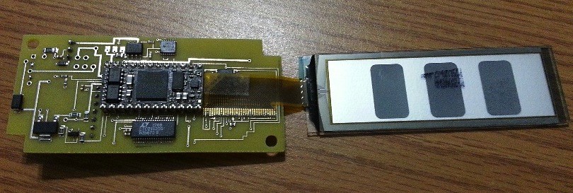
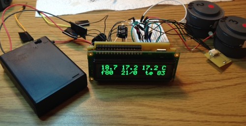
I'm using a 4 x 20 chip-on-glass oled. I had to come up with a library for it on my own.
Power it all with a LiPo inside the box yes? How long before they run out? The housing looks pretty compact and dense (aluminum die cast?), could you really fit a Netduino in there or is it a custom board?
How deep can you go before the gasket of the housing gives in, have you tested that or can you go by the specs of the original product?
Yes, I can power it with a li-ion battery in the compartment that you can just make out at the top with a knurled stainless cap. However, I have instead opted to provide power remotely via the cable. In this way I am able to use two 18650 li-ion batteries. The controller fires a solenoid based on the average of three oxygen sensor readings that you see in the lower right of the display. Voting logic is used to decide the average in the event of one sensor not agreeing with the other two sensors. The solenoid and display together draw a fair amount of power. Two inexpensive 18650 batteries last more than one day's worth of diving.
The housing is machined out of Delrin. The depth rating (without further modification like filling it with fluid) is deeper than most people would ever go -- 300 ft+.
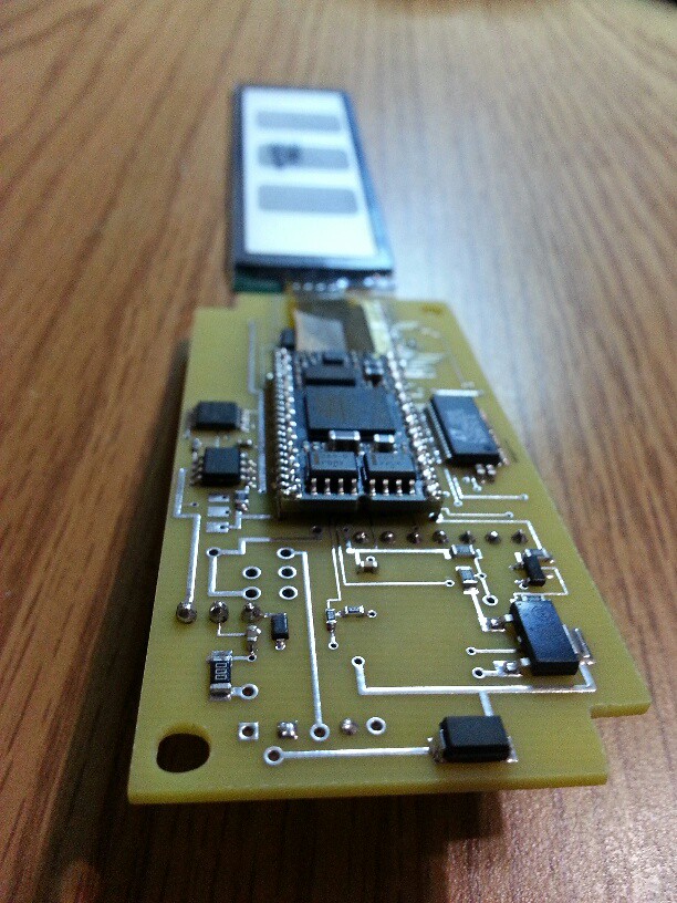
The Netduino Mini inside the handset is mounted on a two-sided custom pcb.
A photo of the top of the main board is shown below. There is also a separate breakout board inside the housing as well that I made to mount the pressure/temperature sensor.
Very nice, I really like seeing the min being used like that. On a board I made, I put a dip24 socket so that I could easily replace it.
Is that a piece of fpc cable between the oled and the pcb? Those connectors are pretty hard to solder so you must be quite handy with the steel.
What's the ssop48 (?) chip doing?
Space (height) has been an issue in my application, so I have stayed away from a dip socket for the mini to date. I flash the mini in situ on the pcb by temporarily soldering leads to it, though.
The chip with a bunch of pins is an LTC2442 24-bit ADC.
Yes, that is fpc cable between the oled and the pcb. It is tricky to solder.
By the way, the smaller transistor on the lower right of the first photo (lower left of the below, second, photo) converts pin 1 to TTL.
Yeah, the socket adds significantly to height
I see, I thought the sot223 was a regulator given the tantalum. So you're using RS232 for deployment and doing level converion of the Rx pin on the other end then?
It's quite impressive to think you etched that board yourself, especially given the pitch of the fpc connector.
Clearly this is not your first pcb by far.
I see, I thought the sot223 was a regulator given the tantalum. So you're using RS232 for deployment and doing level converion of the Rx pin on the other end then?
Yes, exactly.
It's quite impressive to think you etched that board yourself, especially given the pitch of the fpc connector.
Clearly this is not your first pcb by far.
The basic appearance of the board definitely makes it look indistinguishable from homemade, but it's from expresspcb. They have a miniboard service that's pretty reasonably priced. I cut the board out with a dremel. I did a lot of prototyping on pcb's. There were many different versions. For example, I started with standard lcd/oled displays. At one point I was using a breakout board for a preamp that fed into the onboard adc. Flash memory and an RTC were added.
I see, have you tried iTeadStudio? They offer a great value for money service, basically you get 10 PCBs for only 10 USD plus shipping.
Here's an example of a IOIO clone I had them make:
image.jpg135.8KB21 downloadsimage.jpg110.69KB20 downloads
I use Eagle and generate Gerbers which I upload and get the boards about 10 days later.
I'll give iTeadStudio a try in the future. Thanks. Apart from the better value, the colored pcb options are a bonus.
By the way, the video shows the controller/dive computer being put into a surface dive simulation mode. This mode calculates (among many things) the no decompression limit (nd), and, also, once the nd is exceeded, it calculates the decompression ceiling ( c ), time at the ceiling (s), and total decompression time before surfacing (tt). The nd and tt are calculated by simulating an ascent to the surface at the current accumulated dive time (t, in the first line).
In any case, a lot of computations are taking place during the above. At various points I've seen people (not necessarily here) note that doubles and lots of math are not the forte of .NET Micro Framework/Netduino. I would beg to differ...
You said ceiling but wouldn't "floor" be the more appropriate term?
:-)
I've never diven myself but I imagine being able to keep track of nd / tt is crucial since I suppose getting the ascent speed/time right without it can be quite tricky.
Note that the blue color was extra and not included, I think they come in white, black, red and yellow too. Standard color is the regular industrial greenish from back when the iron gate was still intact ;-)
Absolutely amazing!!
I'm a diver myself and have been meaning to attempt this. I'm glad to see someone doingit with a Netduino.
I want to try and create a one button integrated like the Marez Puck I have.
Very well done cys.
What would you have done/used for the casing if you didn't have one? That's my biggest headache.
If I didn't have a case to borrow from something else, I would have gone to emachineshop with a CAD file. I will eventually go down that route. I put the electronics as first priority as that was more of an unknown to me at the outset of the project.
At this point the controller is fully functional in that I have tested it during actual ocean dives (about 5+ hours underwater on the current prototype), and it functions as intended. For those who are not divers, one does not rely on one computer for this kind of diving -- I also have a backup commercial computer that provides independent information. One refinement that I am working on at the moment are improvements to the algorithm for controlling the solenoid based oxygen addition.
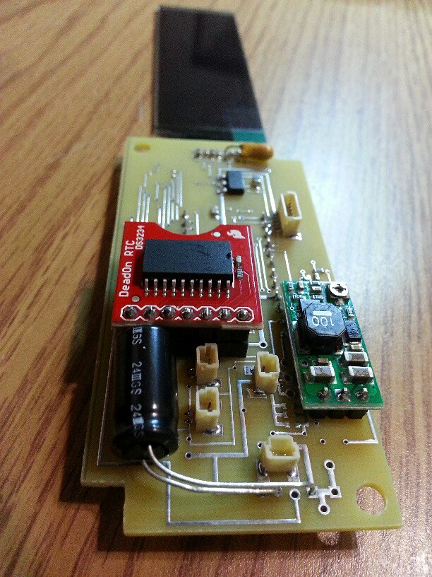
The RTC partly cloaks the tips of the pins of the Netduino mini. The mini iteself is on the other side of this two-sided board. One row of pins from the mini can be seen beginning at the upper left of the green add-on board. I put a header on the RTC to make it detachable. I have to remove the RTC to gain access to another 4 pin receptacle under it. Beyond the receptable, there's an array of caps, resistors, etc, under the RTC as well.
Yes, the green add-on board is a DC-DC converter from Pololu. Specifically it's a 4-25V adjustable boost regulator. In my case it provides 12V from a 3.2 - 4.0V supply.
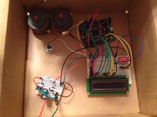
This whole project started out on a regular Netduino and a breadboard. After getting some key things going on the Netduino, I took the project to a pcb with a mini using through hole parts. After one iteration I went to surface mount parts (to the extent possible). I'm about 7 or 8 board revisions into the surface mount version. Revisions mostly focused on adding new capablilties (e.g., RTC, COG-OLED, ADC, etc), which I chose to do incrementally.