Hi
Do you know DIYDrones ?
These are our Arduino-based open source autopilot projects:
* ArduPilot, a low-cost autopilot system for planes.
* ArduCopter, a fully-autonomous quadcopter and heli UAV system.
This can help you...
--
Iliak
iliak's Content
There have been 8 items by iliak (Search limited from 29-April 23)
#9624 Quad.Net Quadrocopter for .NETMF
 Posted by
on 16 February 2011 - 08:16 AM
in
Project Showcase
Posted by
on 16 February 2011 - 08:16 AM
in
Project Showcase
#13451 1024D switch led panel documentation
Posted by
on 19 May 2011 - 04:12 PM
in
General Discussion
Hi,
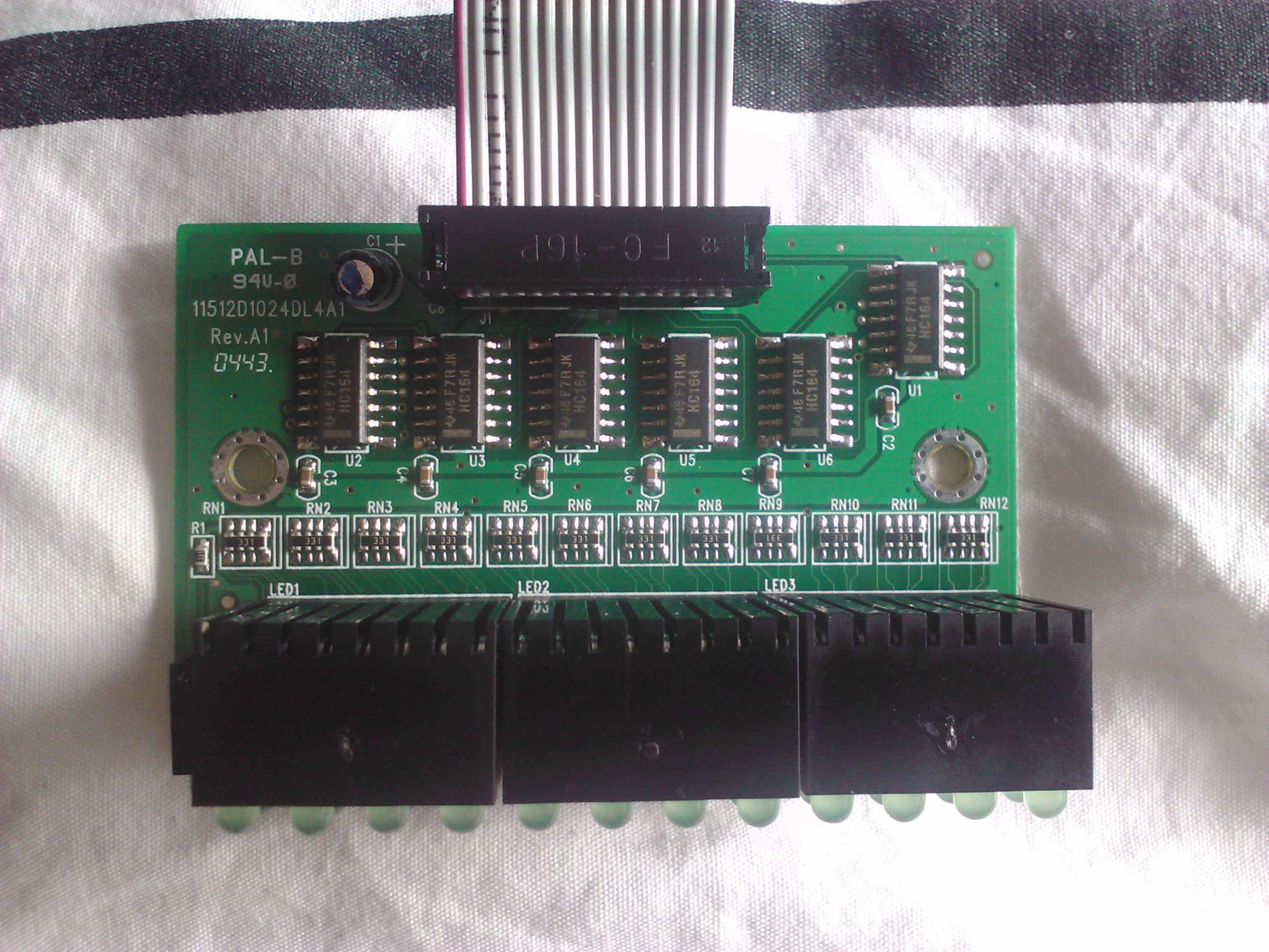
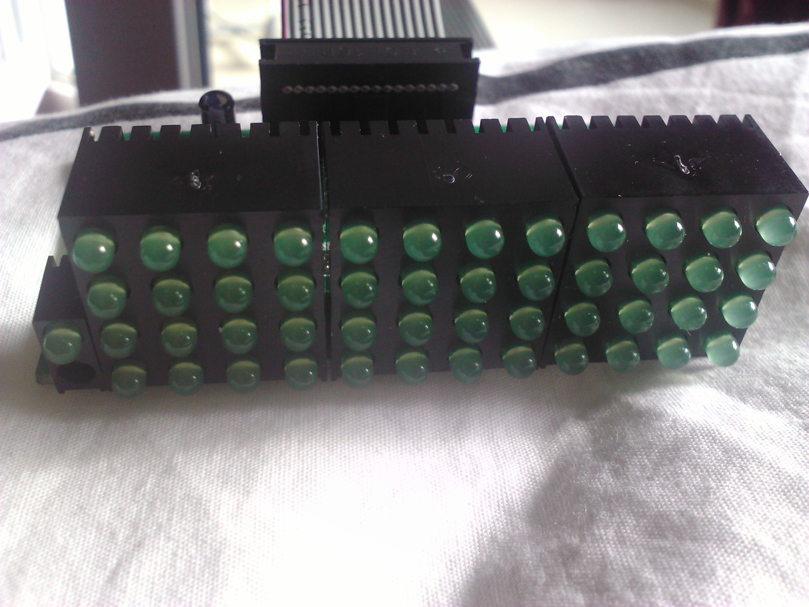
I have a broken DLink "DES 1024D" network switch. I would like to toy with the leds component (on the left side of the switch), but I can't find any documentation on this. Here's some picture of the "thing".
I would be happy if someone can help me on this.
I have a broken DLink "DES 1024D" network switch. I would like to toy with the leds component (on the left side of the switch), but I can't find any documentation on this. Here's some picture of the "thing".
I would be happy if someone can help me on this.
Attached Thumbnails
#13454 1024D switch led panel documentation
Posted by
on 19 May 2011 - 05:10 PM
in
General Discussion
As a quick test, you should be able to turn each LED on by connecting one of the big hole surroundings to ground and resistor net top pads to +5V - resistor nets are those black parts labeled "331" (330 Ω), "top" pad as depicted on the first photo (next to "RN1" labels).
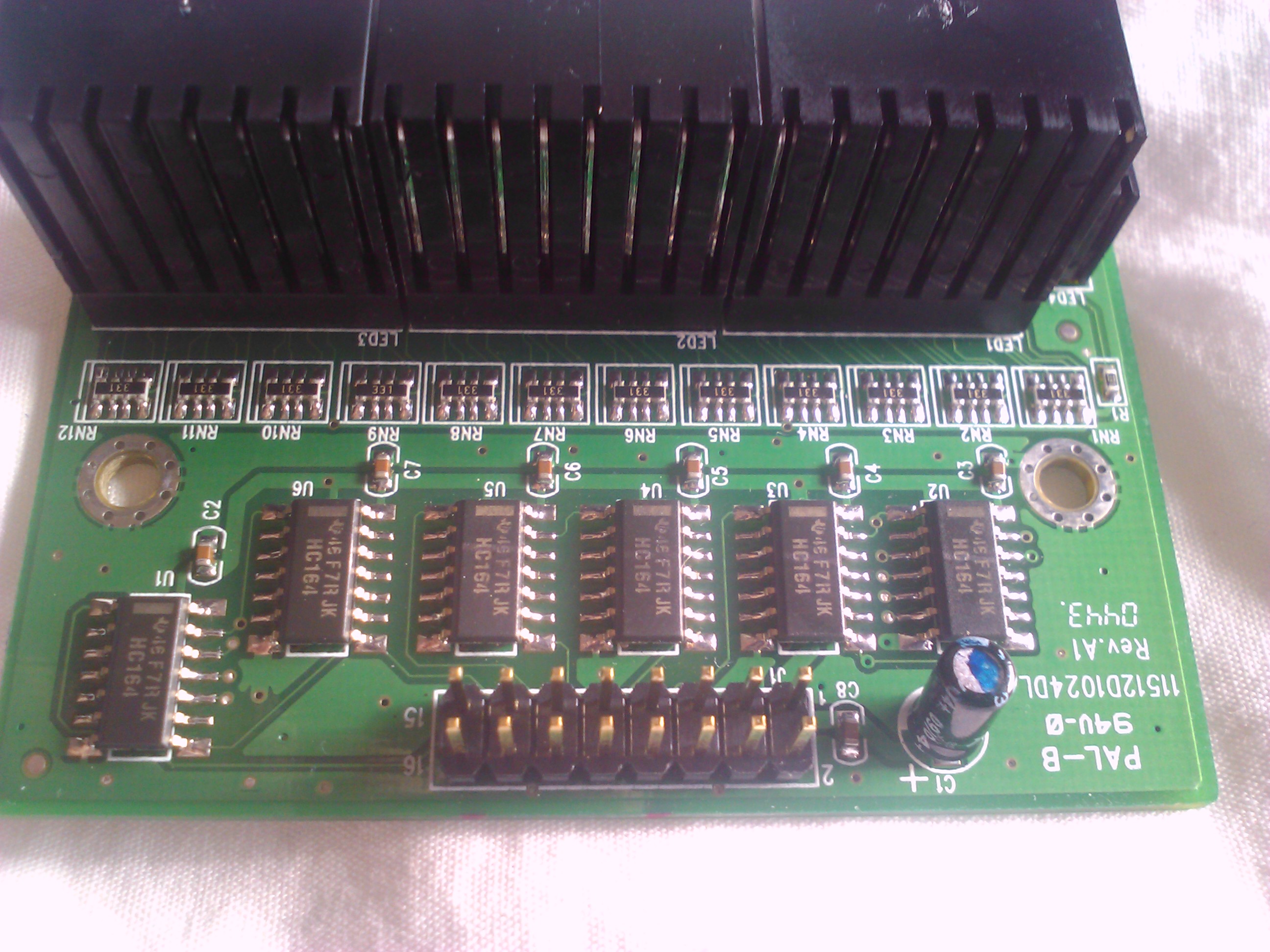
Each group of 16 LEDs ("LED1" .. "LED3" blocks) is controlled by a pair of HC164 8-bit serial-in parallel-out shift registers chained together (16 bits total, U2+U3, U4+U5, U6+U1), you can trace the clock signal from their pin #8 (bottom right, on photo #3) to the connector header pins. Serial data input is connected from the connector pins to U1, U3 and U5 (pin #1). The clear (CLR) pins (#9) are probably not used or broken out to the connector header pins on the bottom side.
This module can be interfaced to Netduino via SPI - just wire clock and data signals and send 16 bits with LED states. 3.3V should be enough for logic H, if the module is powered by 5V.
Ok, thank you for this quick response !!
#13457 1024D switch led panel documentation
Posted by
on 19 May 2011 - 05:38 PM
in
General Discussion
I have drawn some of the connections mentioned in the previous post in the attached image (cyan text is "Serial Data (16 bits)").
Edit: I've made a mistake, the resistor net pads "+5V here to turn on the LEDs" seem to be connected together - so it is in all likelihood already connected to +5V and the LEDs needs to be turned on by connecting the opposite side to the ground.
You read my mind, a picture worth hundreds words !!
Thanks.
#13463 1024D switch led panel documentation
Posted by
on 19 May 2011 - 08:15 PM
in
General Discussion
Just to be sure you don't miss the edit of my previous post, where I made a mistake. The LEDs are connected to +5V (through the resistors) and shift registers act as current sinks - they has to output logic '0' to turn a LED on.
Your guess were corrects, I can light leds. My next step is to use the FC-19P connector.
#13486 1024D switch led panel documentation
Posted by
on 20 May 2011 - 10:01 AM
in
General Discussion
#13502 1024D switch led panel documentation
Posted by
on 20 May 2011 - 09:45 PM
in
General Discussion
This module can be interfaced to Netduino via SPI - just wire clock and data signals and send 16 bits with LED states. 3.3V should be enough for logic H, if the module is powered by 5V.
I can't find any source code / tutorial on this part. Could you show me how to do this please ?
According to this :

Here's how I do :
D0, D1 & D2 => data1, data2, data3
D5, D6 & D7 => clock1, clock2, clock3
Gnd & +5V
using System;
using System.Diagnostics;
using System.Threading;
using Microsoft.SPOT;
using Microsoft.SPOT.Hardware;
using SecretLabs.NETMF.Hardware;
using SecretLabs.NETMF.Hardware.NetduinoPlus;

namespace NetduinoApplication1
{
	public class Program
	{
		public static void Main()
		{
			var button = new InputPort(Pins.ONBOARD_SW1, false, Port.ResistorMode.Disabled);

			// write your code here
			OutputPort Data1 = new OutputPort(Cpu.Pin.GPIO_Pin0, false);
			OutputPort Data2 = new OutputPort(Cpu.Pin.GPIO_Pin1, false);
			OutputPort Data3 = new OutputPort(Cpu.Pin.GPIO_Pin2, false);
			OutputPort Clock3 = new OutputPort(Cpu.Pin.GPIO_Pin5, false);
			OutputPort Clock1 = new OutputPort(Cpu.Pin.GPIO_Pin6, false);
			OutputPort Clock2 = new OutputPort(Cpu.Pin.GPIO_Pin7, false);

			//SPI.Configuration conf = new SPI.Configuration(Cpu.Pin.GPIO_Pin8, false, 0, 0, true, false, 1000, SPI.SPI_module.SPI1);
			//SPI spi = new SPI(conf);

			byte i = 0;
			while (true)
			{

				i++;
				if (i >= byte.MaxValue)
					i = 0;


				//spi.Write(new byte[] { 0x21, 0xBF, 0x04, 0x14, 0x0C, 0x20, 0x0C });


				shiftOut(Data1, Clock1, i);
				shiftOut(Data2, Clock2, i);
				shiftOut(Data3, Clock3, i);

				Thread.Sleep(100);

				//spi.Write(new byte[] { 0x0, 0x0, 0x0, 0x0, 0x0, 0x0, 0x0 });

				shiftOut(Data1, Clock1, 0);
				shiftOut(Data2, Clock2, 0);
				shiftOut(Data3, Clock3, 0);
			}
		}


		/// <summary>
		/// Shift out override (Reverse clock HIGH/LOW)
		/// </summary>
		/// <param name="data"></param>
		/// <param name="clock"></param>
		/// <param name="val"></param>
		static void shiftOut(OutputPort data, OutputPort clock, byte val)
		{

			for (int i = 0; i < 8; i++)
			{
				clock.Write(false);
				data.Write(!((val & (1 << (7 - i))) == 1));
				clock.Write(true);
			}
		}

	}
}
#13511 1024D switch led panel documentation
Posted by
on 21 May 2011 - 08:34 AM
in
General Discussion
After a good night, here's a first working version :
D0, D1 & D2 are connected to data pins
D7 is connected to all clock pins
Is there any source code repository for NetDuino projects I can post the source ?
public class Program
	{
		static OutputPort Data1;
		static OutputPort Data2;
		static OutputPort Data3;
		static OutputPort Clock;
		static InputPort Button;

		public static void Main()
		{
			Data1 = new OutputPort(Pins.GPIO_PIN_D0, false);
			Data2 = new OutputPort(Pins.GPIO_PIN_D1, false);
			Data3 = new OutputPort(Pins.GPIO_PIN_D2, false);
			Clock = new OutputPort(Pins.GPIO_PIN_D7, false);

			Button = new InputPort(Pins.ONBOARD_SW1, false, Port.ResistorMode.Disabled);

			while (true)
			{
				byte size = 16;
				for (int i = 0; i >= 0 && i < size; i++)
				{

					// Lower Clock
					Clock.Write(false);

					for (var b = 0; b < size; b++)
					{
						int mask = 1 << (size - 1) - b;

						var pinState = (mask & 1 << i) != 0;

						// Write data bit
						Data1.Write(pinState);
						Data2.Write(pinState);
						Data3.Write(pinState);

						// Pulse Clock
						Clock.Write(true);

						// Raise Data to prevent IO conflict
						Data1.Write(true);
						Data2.Write(true);
						Data3.Write(true);

						Clock.Write(false);
					}


					Thread.Sleep(250);
					//while (Button.Read()) ;
					//while (!Button.Read()) ;
				}
			}
		}
	}
D0, D1 & D2 are connected to data pins
D7 is connected to all clock pins
Is there any source code repository for NetDuino projects I can post the source ?


