 Posted by
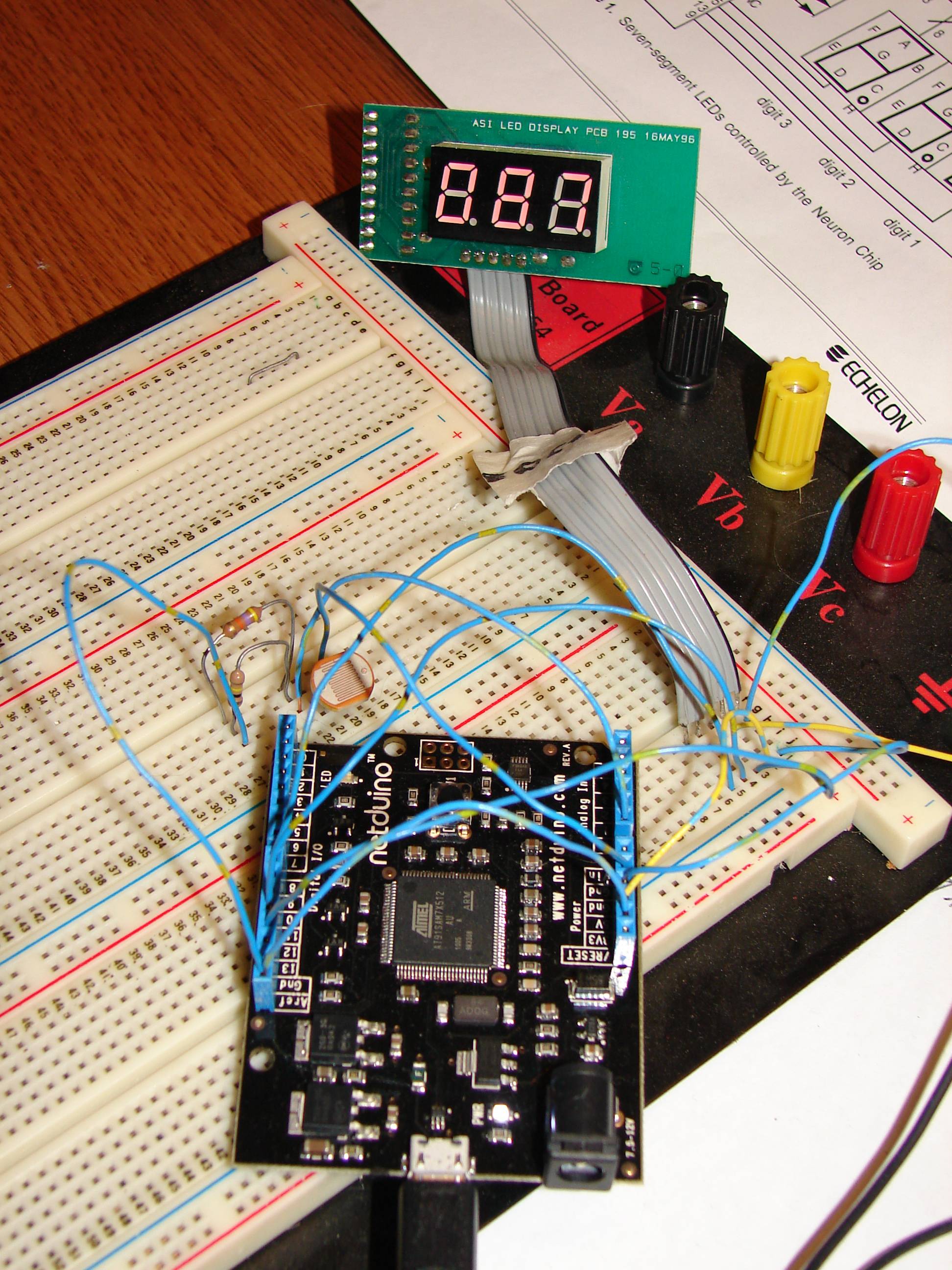
I had an old, defective CO detector with a 3 digit LED display. When I dismantled it, I noticed that the display was driven by an MC14489 chip and a Motorola microcontroller. Using a meter, the Enable, Data and Clock pins were determined. The specifications for the MC14489 chip are online in several places- http://www.rasmicro....mc14489rev4.pdf .
The chip uses two registers to control and display the characters. One is an 8 bit Control register that allows the user to specify whether the characters displayed are HEX numerals or specially decoded alphanumerics. The second register is 24 bits (3 bytes), containing nybbles that specify the characters displayed. Bit 23 to bit 20 (MSB’s) control the decimal points and display brightness. The bits are clocked into the chip MSB first. The controller automatically steers the bits to the proper register, detecting 8 bits or 24 bits. The data in the registers are latched on the low to high transition of the enable line.
Code from http://geekswithblog...nking_leds.aspx is used and modified (simplified, I am much more familiar with VB.Net) to run the MC14489 display. It uses one of the ADC ports to measure the voltage on a voltage divider consisting of a resistor and a cadmium sulphide light dependant resistor to measure ambient light levels.
The ADC data is read 100 times and averaged. The display digit character code is read from a table and ‘OR’ed into the appropriate nybble. A more sophisticated way of displaying characters would involve parsing the HEX and alphanumeric characters from the table and modifying the control register to display the correct character. This could include the ability to display blanks, degrees for temperature and a leading negative sign.
www.echelon.com/support/documentation/bulletin/005-0014-01C.pdf has the code for this kind of parsing.
notEnable is connected to Pin D8
Clock is connected to Pin D12
Data is connected to Pin D11
using System;
using System.Threading;
using Microsoft.SPOT.Hardware;
using SecretLabs.NETMF.Hardware;
using SecretLabs.NETMF.Hardware.Netduino;

namespace MC14489_Driver
{
    class DisplaywithAnalogInput : IDisposable
    {


        private readonly short numDisplayReg = 3;   // MC14489_Driver display registers
        private readonly byte ConfigValue = 0x01;   // hexadecimal code on all
        private readonly byte DecReg = 0xA0;        // decimal and brightness code


        OutputPort notEnable = new OutputPort(Pins.GPIO_PIN_D8, false);
        OutputPort clockPort= new OutputPort(Pins.GPIO_PIN_D12, false);
        OutputPort dataPort=new OutputPort(Pins.GPIO_PIN_D11, false);

        // Initialize analog input for potentiometer
        AnalogInput analogPort = new AnalogInput(Pins.GPIO_PIN_A0);


        public DisplaywithAnalogInput()
        {

            // Set value range to display in 3 digits
            analogPort.SetRange(0, 999);

            // Init the MC14489_Driver Control Register
            SetConfig(ConfigValue);
        }

        public void Run()
        {

            while (true)
            {
                // Read analog value
                var value = analogPort.Read();

                // read 99 more readings
                for (int i = 1; i < 100; i++)
                {
                    value = value + analogPort.Read();
                }
                // calculate average
                value = value / 100;

                // Show the value

                ShowValue(value);

                // Wait a little
                Thread.Sleep(100);
            }
        }


        public void Write(params byte[] buffer)
        {
            if (buffer == null) throw new ArgumentNullException("buffer");
            if (buffer.Length > numDisplayReg) throw new ArgumentOutOfRangeException("buffer too large");

            // Ground notEnable and hold low for as long as you are transmitting the register bytes
            notEnable.Write(false);

            for (int i = buffer.Length-1; i >= 0; i--)
            {
                ShiftOut(buffer[i]);
            }

            // Pulse the notEnable pin high to signal chip to diplay the data
            notEnable.Write(true);
        }

        private void ShiftOut(byte value)
        {
            // Lower Clock
            clockPort.Write(false);

            byte mask;
            for (int i = 0; i < 8; i++)
            {

                mask = (byte)(1 << (7 - i));

                dataPort.Write((value & mask) != 0);

                // Raise Clock
                clockPort.Write(true);


                // Lower Clock
                clockPort.Write(false);
            }
        }


        public void ShowValue(int value)
        {
            int ptr;
            // Map digits to output patterns
            var buffer = new byte[numDisplayReg];
            buffer[0] = 0x00;
            buffer[1] = 0x00;
            buffer[2] = DecReg;

            for (int i = 1; i < numDisplayReg * 2 ; i++)
             {
               byte digit = digits[value % 10];
               if ((i % 2) == 0) //upper nybble - shift 4 bits left
               {
                   digit = (byte)(digit * 16);
               }
               ptr = (i - 1) / 2;
               buffer[ptr] = (byte)(digit | buffer[ptr]);

                value = value / 10; // next digit
             }

            // Write output buffer
            Write(buffer);
        }

        public void SetConfig(byte ConfigSet)
        {
            // Map digits to output patterns
            var buffer = new byte[1];
            buffer[0] = ConfigSet;
            // Write output buffer
            Write(buffer);
        }

        public void Dispose()
        {
            dataPort.Dispose();
            clockPort.Dispose();
            notEnable.Dispose();
            analogPort.Dispose();
        }

        private static readonly byte[] digits = new byte[]
                                                    {
                                                        0x00, // B00000000 = 0
                                                        0x01, // B00000001 = 1
                                                        0x02, // B00000010 = 2
                                                        0x03, // B00000011 = 3
                                                        0x04, // B00000100 = 4
                                                        0x05, // B00000101 = 5
                                                        0x06, // B00000110 = 6
                                                        0x07, // B00000111 = 7
                                                        0x08, // B00001000 = 8
                                                        0x09  // B00001001 = 9

                                                    };
    }
}
Attached Thumbnails
Attached Files
-
 MC14489_Driver.zip 152.15KB
12 downloads
MC14489_Driver.zip 152.15KB
12 downloads


