Posted by
The fun is just beginingThank you for explaining now i understand. Time to play with my netduino!

The next thing you want to do is check out the projects page.
|
||||||||||||||
klotz's ContentThere have been 60 items by klotz (Search limited from 01-July 24) #2321 Analog Input problem
The fun is just begining The next thing you want to do is check out the projects page. #2330 Analog Input problem
Yep, I use Cadsoft Eagle. But don't ask me for help with it. I am just returning to doing hardware after 40 years and am trying to catch up.I just kindof hack away with Eagle until something works. #2316 Analog Input problem
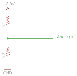
You would need another resister to 3.3Vdc to develop a voltage divider. There is no pull-up in the An-in. #2318 Analog Input problem
First you need to know what the resistance of the photo resister is. Mine was 25k full dark. Second you need to decide if you want it to pull-up or pull-down. I used mine in a pull-up. Then choose a resitance to give you some kind of reasonable current limit, I chose 10K since I just wanted to play. So using the attached schematic, I put the photoresister in a R1, a 10k in R2, you can try it either way and pick the one you like. Attached Thumbnails#708 Analog Tutorial?
The new version is working for me so far. I am using it with the SparkFun Joystick shield. http://www.sparkfun....oducts_id=9760. This is the one I was having problems with on Sat. Thanks for the update! #2411 Buzz a piezo speaker?
The problem is that when a pwm period and duration are the same the output is high. Period is the rising edge to rising edge time of the output wave form. While duration is the length of the high time of the period. So period should be 1/frequency and duration should be (duty_cycle * period) where duty cycle is some value < 1. Also if I remember correctly, period is in microseconds so:
Try var period = (uint)(1000000 / frequency); pwm.SetPulse(period, period/2); I used the same buzzer and I just checked my code and the period is in microseconds like I remembered. #3506 Compatible Shields and Accessories
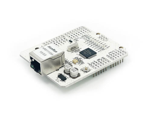
Add the following Wiz5100 ethernet shield
http://www.seeedstud...l?cPath=101_102
also available from
http://www.nkcelectr...eeedstudio.html
Like the latest Arduino Ethernet shield it requires an ISPC connection.
Sorry about that, I found the schematic and it will work without the ISPC. There are three zero ohm resister used as jumpers that just have to be moved to convert from ISP to DI MOSI. Duh!

Attached Thumbnails#2144 Compatible Shields and Accessories
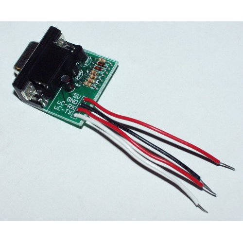
Not a shield but I need it so some one else may need one as well http://www.sparkfun....products_id=133, RS232 shifter. It converts from digital to RS232 sufficiently to work with a PC.
Just don't forget to use 3.3 Vdc for VCC or you could spend a whole afternoon troubleshoot the hardware ( I wonder how he knew that?
 ) )
Attached Thumbnails#2145 Compatible Shields and Accessories
Well when it comes to prototype shields, there is not much that can go wrong, but thought I would add this one anyway. NKC Electronics has http://www.nkcelectr...hield-kit.html. The only caveat is that you don't want to install the 6-Pin ICSP pass thru. Itdoesn't work with the Netduino anyway since it's not populated

Attached Thumbnails#2422 Controlling a LED Intensity
Use a PWM. You can then control the brightness by changing the duty cycle (duration). I would reference the articles in this forum but you can't search for PWM or LED because of the search rules

#10103 Controlling multiple LEDs with a few outputs as possible
I have had some success using I2C and I have the data sheet for the MCP23017 here in front of me so I think you are doing things right. I will have to get my hands on one the the chips to be sure.
First, the address should be in the range of 0x20 - 0x27. With the way it is wired, assuming the drawing is correct, the address of the configuration should be 0x20. It appears that you have this right, but let me explain for those who may not be aware. The I2C address as used by the I2CDevice.Configuration is the 7-bit address. With some other interfaces for I2C, it is common to list two addresses for a device, one write address and one read address. The two addresses differ only in the lsb, where an even number is the write address and an odd number is the read. In the case of those interfaces, the address would be 0x40 for Write and 0x41 for Read. This gets more confusing since some datasheets list the addresses as the Read/Write address, for instance Newhaven displays and the Sparkfun MPR121 use this method. In those cases to use the device you will often see new I2CDevice.Configuration(ADDR >> 1, 100); Second, according to the data sheet, when using the I2C device the speeds are 100kHz, 400kHz and 1.7 MHz so that is correct. Now for the final point. I will admit that at this time I am just a compitent C# programmer. But I generally avoid using "var" when I know the data type. So, I would avoid using:
var setIOCON = I2CDevice.CreateWriteTransaction(new byte[] { IOCON, 0x24 });
instead I would have used:
I2CDevice.I2CTransaction setIOCON = I2CDevice.CreateWriteTransaction(new byte[] { IOCON, 0x24 });
Other than that I will see what I can do about duplicating you hardware and see if I can find something else. #10157 Controlling multiple LEDs with a few outputs as possible
I got your latest code to work by adding a pull-up resister on ~RESET(pin18). Not too obvious in the description in table 1-1 "Hardware reset. Must be externally biased"
I sort-of had it working without the pull up but it was not reliable. Once I put the resister in there, it became extreemly reliable.
Sorry I didn't notice this before.
And by the way, I had it working without any of the code changes I suggested.
http://www.vimeo.com/20357391
#3649 Experimental Drivers for Wiznet-based Ethernet Shields
Well after killing one of my Netduino's, I have managed to add listen, bind and accept to the experimental drivers. I think there is a disconnect between the implementation in the Wiz5100 chip and WinSock or Berkley Sockets. So based on my implementation you can only receive one connection request. Maybe someone can find where I am going wrong and post an update.
I have changed the namespace so I could keep my changes separate from the original SecretLabs implementation.
EDIT KLOTZ: Update the implementation of the bind/Listen/accept code based on some more reading. Also change the test code. Still does not reconnect.
Attached Files
#3659 Experimental Drivers for Wiznet-based Ethernet Shields
I can't be sure without more details, so I appologize for asking the obvious question, 1) do you have the board connected to a 192.168.11.x network? 2) Have you posted a request from a client computer, "http://192.168.11.98"? The code waits for a connections from the client, the loop you mentioned so is blocked. #3721 Experimental Drivers for Wiznet-based Ethernet Shields
updated the code. I found I was not doing the bind/listen/accept cycle correctly. Not sure I have it right yet, I still can't connect more than once. Hope someone could tell me where I am going wrong.
#3740 Experimental Drivers for Wiznet-based Ethernet Shields
I would never have thought to do it that way. I am used to using sockets under WinSocks and you would not normally have to recreate the socket to get a new connection. It looks to me like it is not dropping the connection when I close the socket. Your solution causes the socket to be desposed and that may explain why it works. #3668 Experimental Drivers for Wiznet-based Ethernet Shields
That is a very good point. I did have a problem with my Seeeduino Ethernet board, it would not accept any of the commands. It turned out that I could do one of two things, add an ICSP connector to my Netduino or change some soldered jumpers on the board. You may want to check to see if the enthernet board has jumpers. The best place to look would be on the schematic. #3171 Experimental Drivers for Wiznet-based Ethernet Shields
That is a good suggestion. However, you may want to be careful about using an address that will be on the same network segment as the shield. Some ethernet devices count on all the addresses on the same segment being unique. Another good source of unique mac addresses would be defunct or dead network devices you may have laying around. MAC addresses are generally printed on the serial number label and if they are truly defunct/dead you can be certain that the address is unique. #3158 Experimental Drivers for Wiznet-based Ethernet Shields
Yes the shield pings just fine.
>ping 192.168.11.98
Pinging 192.168.11.98 with 32 bytes of data:
Reply from 192.168.11.98: bytes=32 time<1ms TTL=128
Reply from 192.168.11.98: bytes=32 time<1ms TTL=128
Reply from 192.168.11.98: bytes=32 time<1ms TTL=128
Reply from 192.168.11.98: bytes=32 time<1ms TTL=128
Ping statistics for 192.168.11.98:
Packets: Sent = 4, Received = 4, Lost = 0 (0% loss),
Approximate round trip times in milli-seconds:
Minimum = 0ms, Maximum = 0ms, Average = 0ms
I should add that I am using the original Arduino shield with no SD card.
#3149 Experimental Drivers for Wiznet-based Ethernet Shields
I am having the same results. 10060 when running the wiznet test app from here. I am sure we are missing something basic but have no clue what it could be.

#3160 Experimental Drivers for Wiznet-based Ethernet Shields
I had read that DNS was not working, but I thought that was the purpose of the proxy in the following segment from the Wiznet test posted in this forum.
            string url = "http://www.secretlabs.com/default.htm";
            // NOTE: since this experimental release does not support DNS yet, we must use the IP address of the web server as the proxy address.
            string proxy = "174.143.45.105"; // ip address of secretlabs.com

            // If the device must go through a proxy server, then set proxy to the
            // fqdn or ip of the proxy server.
            try
            {
                String html = GetWebPage(proxy, url, 80);
                Debug.Print(html);
            }
            catch (SocketException se)
BTW I don't require a proxy server to access the net. #3172 Experimental Drivers for Wiznet-based Ethernet Shields
I did a quick check of the standard, maybe the problem is that the first byte has the least significant bit set which means broadcast. Routers generally will not propagate a broadcast by default, for many good reasons. I don't know why I didn't notice it before, must be because it is getting late. Since my network here at home is three tiered, my first jump would have been blocked. I was just luck that my pc and the 'duino were on the same segment(switch). #3345 Experimental Drivers for Wiznet-based Ethernet Shields
Sure. I would be willing. I did want to get around to a Neduino plus when they start shipping again and if this is a way to make sure the network is up and running I'll do my part. Just need some pointers to the code base and away we go
#3328 Experimental Drivers for Wiznet-based Ethernet Shields
Chris add me to your list of volunteers. I have worked on a project were we implemented uIP on an HC12 using the enc... chip so I have some experience with networking in sockets. (though I will admit to being a newbie at C# I have extensive experience in C++). I just spent the last 2 hours getting bind and listen implemented and ran into a glitch on accept so I do want to help. #3383 Experimental Drivers for Wiznet-based Ethernet Shields
I think this is the proper close code
        internal void Close(int socketIndex)
        {
            UInt16 socketBaseAddress = (UInt16)(0x400 + (socketIndex * 0x100));

            // issue command to close the socket
            // socket n command register (Sn_CR)
            WriteRegister((UInt16)(socketBaseAddress + 0x0001), 0x10);
            while (ReadRegister((UInt16)(socketBaseAddress + 0x0001)) != 0) ; // wait to process the command
            lock (m_SocketsLock)
            {
                m_Sockets[socketIndex] = null;
            }
        }
| ||||||||||||||
|
||||||||||||||
| This webpage is licensed under a Creative Commons Attribution-ShareAlike License. | ||||||||||||||