 Posted by
This is my circuit

and the actual setup on a breadboard

Installed:
Microsoft Visual C# Express 2010
Microsoft .NET Micro Framework v4.1 SDK
Netduino SDK v4.1
Putty
EDIT: Uhm nevermind i was in the wrong putty options >_>!
|
||||||||||||||
bpkdasbaum's ContentThere have been 12 items by bpkdasbaum (Search limited from 22-June 23) #20994 Getting started with Netduino Mini (early instructions)
I am trying to setup my netduino mini, but when i press open port in putty, i get windows blip and nothing happens, no error message. What am I missing?
This is my circuit and the actual setup on a breadboard Installed: Microsoft Visual C# Express 2010 Microsoft .NET Micro Framework v4.1 SDK Netduino SDK v4.1 Putty EDIT: Uhm nevermind i was in the wrong putty options >_>! #19573 TRON Identity Disc by Harford Hackerspace
Posted in other topic and SOLVED HERE
Also new updated schematics available + further details and links to the build =============================== =============================== Hi, I am in search of help with the Tron Disc Project. First of all, I don't know jack about programing or electronics, but I'm a quick learner. I am currently following the two guides here: Original Guide Hackerspace/Coding4fun Thundergod Guide using netduino mini 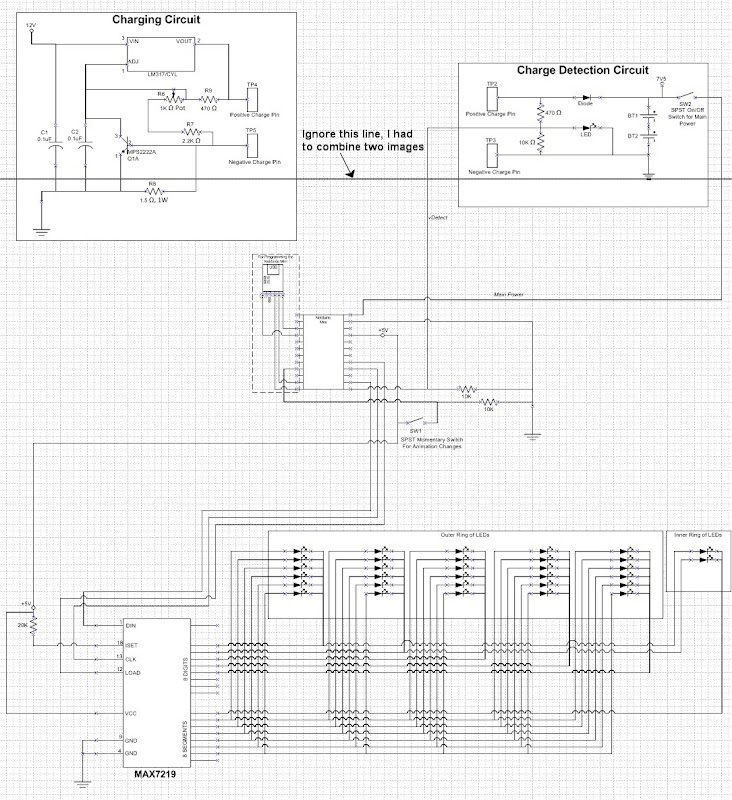 This is the basic circuit. But I would like to alter the following: - use a premade USB charger unit like this: sparkfun micro usb charger - Data sheed with schematic here - add more LEDs: 30 outer ring, 16 inner ring (8 on each side) and 8 for the solo lights with bezel mounts on the inner surface of the disc (4 on each side) = total of 54 The basic idea is to create the same animation as in the movie (youtube link @ scene 34 sec). Now the questions are: - Can I simply smolder the usb charger directly to the netduino and and attach >>both<<??? battaries onto that one charger? If yes can you please clarify how the batteries should be wired/smoldered to the usb charger? - If I go with 54 LEDs: - Do I need other batteries? I bought 54 x nichia 6500mcd 45° - data sheet here - If the batteries stay the same, will my LEDs simply run out of power faster or are they going to shine less bright? - If they shine less bright, what battery do i need? Thanks in advance #20452 Need help with electronics please
Update:
I found a balance charger circuit in an rc forum! Can anyone tell me if it will work like this? I was already told i need to "adjust/change the resistors divider of LM2577" in the charging circuit , no idea how to do that yet eagle schematic here 
#20460 Need help with electronics please
the original circuit had the same switch and it was supposed to be working while charging (even had an extra animation, thats what the charging detection circuit is for). From what i read about lipo batteries it is possible to power a circuit while charging. #20286 Need help with electronics please
Woot sry, missed you in the chat, seen you leave the chat just now >_>
#20459 Need help with electronics please
#20247 Need help with electronics please
Okay, now you lost me completely ^^
From what i learned today about charging multi cell lipo batteries, it is possible but dangerous and both batteries need to be checked by the factory to be usable together ... and even then they require a rather complicated charger. Found it here. I have also found some multicell chargers but they are all huge. Frankly i don't even understand how they made it work in the original design O_o? == LEDs Voltage == I found out how to set the output voltage for the max7219 from the data sheet (table 11). The Resistor (R1 in the schematics) needs to be ~24kohm for 3.2V. Yay \o/ ... So the max takes in 5v from the netduino and passes on 3.2v to the Leds.
Another alternative would be to find a rechargeable battery that has an output of 5V or 9-12V right? Since the netduino can be powered by either. I'll check if I can find something like that. EDIT: I am wondering how other ppl use their netduino??? can't find anything on power source related problems ... am I the only one who wants a circuit to run through usb and a rechargeable battery like a cellphone ^^??? I thought this technology is quite common now days? Even my PC Mouse is working that way, has a 1.2V rechargable battery, but is chargable via usb which is 5V. Or am i missing something here?  Edit 2: Uh actually found someone: netduino forums link #20022 Need help with electronics please
Copy Paste from Showcase (seems like noone reads it there, since the original post is quite old).
Hi, I am in search of help with the Tron Disc Project. First of all, I don't know jack about programing or electronics, but I'm a quick learner. I am currently following the two guides here: Original Guide Hackerspace/Coding4fun Thundergod Guide using netduino mini This is the basic circuit. But I would like to alter the following: - use a premade USB charger unit like this: sparkfun micro usb charger - Data sheed with schematic here - add more LEDs: 30 outer ring, 16 inner ring (8 on each side) and 8 for the solo lights with bezel mounts on the inner surface of the disc (4 on each side) = total of 54 The basic idea is to create the same animation as in the movie (youtube link @ scene 34 sec). Now the questions are: - Can I simply smolder the usb charger directly to the netduino and and attach >>both<<??? battaries onto that one charger? If yes can you please clarify how the batteries should be wired/smoldered to the usb charger? - If I go with 54 LEDs: - Do I need other batteries? I bought 54 x nichia 6500mcd 45° - data sheet here - If the batteries stay the same, will my LEDs simply run out of power faster or are they going to shine less bright? - If they shine less bright, what battery do i need? Thanks in advance #20122 Need help with electronics please
I kind of thought small single cells are safe to use if charged correctly and also wired correctly into a circuit.
I mean the original one worked ... and it was made by guys from this forum. also afaik the newer cellphones all use lipo cells as a battery?
Also, is there an alternative? I mean i went for lipo not only because they were in the original design, but also because they are small and fit into the disk.
The idea is to make the whole disk chargable without taking out the batteries everytime and thus even use it as a decorative lamp at home.
#20196 Need help with electronics please
Thanks for the help so far Mario.
Update: I like the idea of only 1 lipo battery. Lipo Battery I wanted to use: 850mah 2c 3.7V Will this be enough for the 50 LEDs? I prepared and new Schematic ... was a pain in the ass to learn how to use a circuit diagram program :E but it was worth it. The Schematic is far from being completed though. - Don't know how to connect the battery directly to the max and the LEDs O_o? Do I need another Step Up Module for that too? At the moment it looks like it is powered over the netduino with 5V ... or do you mean by "no conversion" that it will run just fine with 3,7 too directly from the battery too? - Don't know how the step up module will look like. I found a premade version with a build in potetiometer, supposed to be regulating from output 2V-35V and input ... this will take some time to research for me, already had a quick peek at it though. If i understood correctly i can switch the potention meter from 10k ohm to 1k ohm, since i only need to set it up from 3,7 to around 9 volt for easier adjusting - GND is Ground ... where does this go in the actual setup, do i have to wire it somewhere, if yes where to? Guess this one is total noob question - Don't know if i copied the wires correnctly going from arduino to the mx7219 . Don't know if I set up the LEDs correntcly, since i added more to the original design, i simply expanded it though, so it should be fine And in case anyone wants to adjust the schematic and contribute, here is the .sch for Eagle: Schematic Download on Megaupload for Eagle 
#20234 Need help with electronics please
== LEDs / Battery ==
Nichia 5mm LED white 6150mcd 45° NSPW510DS Current 10 mA 20 mA 30 mA Voltage 3,00 V 3,20 V 3,30 V light power 3075 mcd 6150 mcd 9225 mcd So 50x20mA = 1000mA ... meaning i could power the whole disk nonstop for about 45min before recharging. Thats plenty of time. And at home it will be connected to usb anyway the whole time as a lamp near my pc. == Max7219 == I though the whole purpose of the chip was to give the right voltage to the targeted bits/leds? It says on Maxims homepage Only one external resistor is required to set the segment current for all LEDs. So that shouldnt be problem right, since the resistor is alrady set (20k ohm in the original schematic). But then again, this is only my assumption, with my limited electronics knowledge >_> Within the original design it looks to me like it is going from two battaries 7.4V to the netduino, then the netduino has its own 5v out going to the max, and the max is set to 3,5V output (thats the volatage of the LED used in the original design) through the resistor at the build in converter or something. My LEDs need only 3,2V, guess I'll need another resistor then? #20283 Need help with electronics please
Ugh ...
I was following up on your first post Mario, when you said:
Amd I just found out 2 things: 1. netduino microcontroller max current: 200 mA total 2. USB max current: 500 mA  Since I need 1000 for the LEDs alone 80 something for the netduino and probably another 80 for the max7219, I won't be able to run this thing via USB. Guess my dreams just got shattered :L So back to square one. No USB charger. Back to two batteries. Will try using the charging and charge detechtion circuit from the original design >_> but add a step down from batteries -> max7219 instead of batteries -> netduino -> max7219 as you already suggested. I will need a step down from 7.4V to 5V then. I also checked out the charging circuit and it was designed by someone who knows what he is doing. It is indeed a way to charge 2 cells in series. I've been checking his circuit against mine and found out what i need to alter to use it for 7.5 batteries. Well basically it was already set correct in the original deisgn fron Harford Hackerspace guys. But I was actually able to understand it and recalculate the resistors and voltage, since it is explained in detail on shdesign.org  ... Even the 7.5V enrty makes sense now to me \o/ yay. ... Even the 7.5V enrty makes sense now to me \o/ yay.In case you're interested: Main article on the charging circuit In depth explanation Original schematic Improved Schematic Things to do now: - find matching stepdown module or parts for atleast 1A (50x20mA) - order battery - order female dc connector - order stepdown module / parts - prototype and test that it actually works (also check voltage, set pot, etc.) - then finally build it >_> New Schematic 
| ||||||||||||||
|
||||||||||||||
| This webpage is licensed under a Creative Commons Attribution-ShareAlike License. | ||||||||||||||


