Hi!
First of all sorry if the terms in the post won't be technically correct, english is not my main language, but I'll try my best.
I'm working on a project and came to a point where I need to read data from the device, and I'd like to have that data in the array so I can work with that data programmatically in Netduino to continue the project.
The device I have sends data over 3 pins: CLOCK, DATA and LOAD (it is meant to be read by OKI Semiconductor MSM6775 if it's any help). The data format is something like SPI but with one difference - the DATA is in 8 bit words but LOAD signal is every 11 words. Complete data frame consist of 4 packets of these 11 words (ends with 4th LOAD signal and then it's aprox 31,4ms gap between new data frame). So I'm looking for a way to have that data frame in an array of 352 elements (4*11*8).
And this is where I'm stuck. Is it possible to do this with Netduino? How can I trick it into reading this as SPI when Netduino works as SPI master? Is there a way to send "false" load signal every 8 bits?
Any help would be much appreciated!
Thanks,
Yemi

Help with reading what looks like SPI but isn't
Started by Yemi, Dec 02 2012 12:22 PM
5 replies to this topic
#2

Arron Chapman
-

- Members
-

- 289 posts
Advanced Member
- LocationOregon, USA
Posted 02 December 2012 - 05:01 PM
Welcome to the community! Like most people who are self conscious about it your English was better than most native speakers.Hi!
First of all sorry if the terms in the post won't be technically correct, english is not my main language, but I'll try my best.
I'm working on a project and came to a point where I need to read data from the device, and I'd like to have that data in the array so I can work with that data programmatically in Netduino to continue the project.
The device I have sends data over 3 pins: CLOCK, DATA and LOAD (it is meant to be read by OKI Semiconductor MSM6775 if it's any help). The data format is something like SPI but with one difference - the DATA is in 8 bit words but LOAD signal is every 11 words. Complete data frame consist of 4 packets of these 11 words (ends with 4th LOAD signal and then it's aprox 31,4ms gap between new data frame). So I'm looking for a way to have that data frame in an array of 352 elements (4*11*8).
And this is where I'm stuck. Is it possible to do this with Netduino? How can I trick it into reading this as SPI when Netduino works as SPI master? Is there a way to send "false" load signal every 8 bits?
I don't think you even need to do any tricks. I looked through the datasheet you linked to and I think that if you use the following SPI configuration, along with mannualy managing the LOAD pin you'll be set.
SPI.Configuration Device1 = new SPI.Configuration(
    Pins.GPIO_NONE, // SS-pin
    false,             // SS-pin active state
    0,                 // The setup time for the SS port
     0,                 // The hold time for the SS port
    true,              // The idle state of the clock
    true,             // The sampling clock edge (HIGH)
    1000,              // The SPI clock rate in KHz
     SPI_Devices.SPI1   // The used SPI bus (refers to a MOSI MISO and SCLK pinset)
);
Then you can transfer your data as you need to with spi.Write(data) after you Write every 11 words, then manually pulse the LOAD pin;
OutputPort LOAD = new OutputPort(Pins.GPIO_PIN_x, false);
...
LOAD.Write(true);
Thread.Sleep(1);
LOAD.Write(false);
If I've understood that datasheet that should work for you.
- Yemi likes this
When you talk EE use small words, I'm just a Software Developer 
My Blog/Site and Everything Else
If my post helped you please consider pressing the "Like This" button in the bottom right-hand corner.
Oh my. So many things, so little money!!
#3
Yemi
-
- Members
-
- 5 posts
New Member
Posted 02 December 2012 - 06:29 PM
Thank you for the welcome and for a quick and detailed reply!
I've been reading your answer and it seems to me that this will work the other way around then I need it to work.
Netduino is suppose to read those 11 words, not send them. I get a clock, data and load signal from a device and am trying to send them to netduino so it can read them and store in an array(instead of the MSM6775). The problem is that I read in the wiki that netduino is the master and as master it is the one that sends the clock, data and load signal, not receives it.
I was looking at this option for reading the data but I'm not sure if it will work:
"The SPI bus is full-duplex. That means that data is sent simultaneously in both directions. The bus is controlled by the bus master, in this case the Netduino. The slave device cannot send data back unless the master generates the clock pulses. So whenever we want to read data we need to send enough clock pulses to get the data we want out. At the same time as the slave is sending data on its DOUT or MISO line, it is also reading whatever is on its DIN or MOSI line, even if this is 0xFF (all ones) or 0x00 (all zeros). So you cannot read without writing to the slave at the same time. That is why there is no SPI.Read() function."
As far as I understood it, if netduino sends 11 byts of clock pulses same frequency as the device has, it will read 11 words back, but the chances that timing of netduino reading the data and device sending it at the same time are probably close to none.
I found another idea in this project that is similar to what I'm trying to do: http://www.overkills...s.com/id14.html, with difference that I won't be displaying the data on another segment display. That's why I need that data in the netduino and I'll process it in another way later on.
At the end of the page it is explained how to trick the chip into reading data as SPI with false LOAD signal every 8 bits, but this would need netduino to work as SPI slave to read it and I know it's not that easy to do.
#4
Arron Chapman
-
- Members
-
- 289 posts
Advanced Member
- LocationOregon, USA
Posted 03 December 2012 - 03:06 AM
Sorry about that I thought you were replacing the device which was sending the data.Thank you for the welcome and for a quick and detailed reply!
I've been reading your answer and it seems to me that this will work the other way around then I need it to work.
Netduino is suppose to read those 11 words, not send them. I get a clock, data and load signal from a device and am trying to send them to netduino so it can read them and store in an array(instead of the MSM6775). The problem is that I read in the wiki that netduino is the master and as master it is the one that sends the clock, data and load signal, not receives it.
I was looking at this option for reading the data but I'm not sure if it will work:
"The SPI bus is full-duplex. That means that data is sent simultaneously in both directions. The bus is controlled by the bus master, in this case the Netduino. The slave device cannot send data back unless the master generates the clock pulses. So whenever we want to read data we need to send enough clock pulses to get the data we want out. At the same time as the slave is sending data on its DOUT or MISO line, it is also reading whatever is on its DIN or MOSI line, even if this is 0xFF (all ones) or 0x00 (all zeros). So you cannot read without writing to the slave at the same time. That is why there is no SPI.Read() function."
As far as I understood it, if netduino sends 11 byts of clock pulses same frequency as the device has, it will read 11 words back, but the chances that timing of netduino reading the data and device sending it at the same time are probably close to none.
I found another idea in this project that is similar to what I'm trying to do: http://www.overkills...s.com/id14.html, with difference that I won't be displaying the data on another segment display. That's why I need that data in the netduino and I'll process it in another way later on.
At the end of the page it is explained how to trick the chip into reading data as SPI with false LOAD signal every 8 bits, but this would need netduino to work as SPI slave to read it and I know it's not that easy to do.
Unfortunately the .Net Micro Framework does not support SPI Slave so your project is going to be a bit more complicated. I think that with some careful interrupts you might be able to make this work I'm not in front of a computer with Visual Studio at the moment so I can't write up some code, but this is what I'm thinking you may be able to do.
Create an Interrupt for the Clock line and the load line, both interrupt on logic high.
When you receive an interrupt on the clock line read the value of the data line and store it.
When you receive an interrupt on the load line, take all of that data you've stored from the other interrupt and use it to recreate the data.
I don't know if it'll be possible to do this fast enough to get the data, do you know the speed of the clock that you'll be listening to?
When you talk EE use small words, I'm just a Software Developer
My Blog/Site and Everything Else
If my post helped you please consider pressing the "Like This" button in the bottom right-hand corner.
Oh my. So many things, so little money!!
#5
CW2
-

- Members
-
- 1592 posts
Advanced Member
- LocationCzech Republic
Posted 03 December 2012 - 08:25 AM
One thing to keep in mind is that in .NET MF interrupts are queued, so reading the value of the data line in clock interrupt does not return the state of the data line when the clock interrupt has occured, but the state of the data line when the interrupt handler is executing, which can be a few milliseconds later. I think it could be done by configuring the interrupts for both edges, storing the timestamps in buffers and then reconstructing signal levels based on pulse durations (the number of interrupts is known, fixed frame size). But I am afraid the performance will not be great, my guess would be around ~10 kHz.When you receive an interrupt on the clock line read the value of the data line and store it.
When you receive an interrupt on the load line, take all of that data you've stored from the other interrupt and use it to recreate the data.
#6
Yemi
-
- Members
-
- 5 posts
New Member
Posted 03 December 2012 - 06:32 PM
Thank you both for your answers!
I've recorded the signal with bus pirate, and if I counted it right, clock has 400kHz frequency, Clock HI time is 1.5us and clock LO is 0.75us (according to what the bus pirate recorded). Gap between words is 3us. Will netduino be able to read it as 3 separate digital signals on interrupt mode or is it too fast? Here is the pic what the signal looks like:
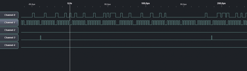
I've recorded the signal with bus pirate, and if I counted it right, clock has 400kHz frequency, Clock HI time is 1.5us and clock LO is 0.75us (according to what the bus pirate recorded). Gap between words is 3us. Will netduino be able to read it as 3 separate digital signals on interrupt mode or is it too fast? Here is the pic what the signal looks like:


0 user(s) are reading this topic
0 members, 0 guests, 0 anonymous users


