The Netduino forums have been replaced by new forums at community.wildernesslabs.co.
This site has been preserved for archival purposes only
and the ability to make new accounts or posts has been turned off.
I have a nice lathe, and I would like to upgrade my lathe to have digital readouts (DRO) for the axis positions.
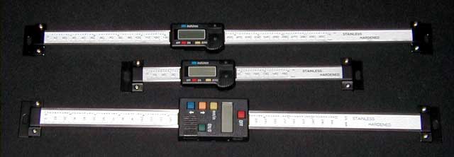
There are turnkey options available, but I thought it would be really cool to create something myself, based on the cheap chinese digital calipers that you can buy for approx $15 for a 15 centimeter long version.
Example:
The cool thing about these calipers is, that they have an output port, that outputs the caliper measurements.
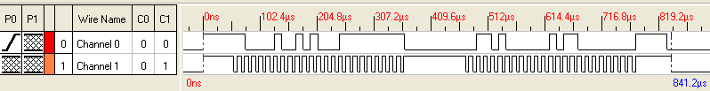
The output is described here: shumatech website
Example logic output:
My question is, can the netduino be used to read and translate the signal?
Eventually netduino should display the measurements on a screen, but that's the easy part I guess .
My question is, can the netduino be used to read and translate the signal?
Eventually netduino should display the measurements on a screen, but that's the easy part I guess .
Thanks in advance for the replies!
There's actually quite abit of information out there if you enter the same URL into google.
Actually anything can be interfaced to anything if you throw enough support components at it. Some posts I have read that as a DRO device this would basically suck at you only get three readings a second; so when you are doing fine adjustments you could find you self chasing readings back and fourth.
Can the netduino support this device directly? I would say no on a number of different levels, see quotes extracted from the internet:
Most micros use VSS*0.7 for logic high, so a processor that runs at
5V needs at least 3.5V. A processor that runs at 3.3V needs 2.3V .
This is why I mentioned that the caliper output at 1.5 for logic
high would be a problem.
Other reports of the protocol being SPI master without chip select, again not something supported by netduino.
There are some people over on AVRFreaks who have had success with dedicated processors and assembly code.
My question is, can the netduino be used to read and translate the signal?
Obviously, this could be easily done via SPI, but unfortunately the current .NET Micro Framework implementation does not support Slave mode, which is required to read/receive data in this scenario (the calipers acts as SPI Master). At this time I am not sure what would be the complexity of firmware code to enable SPI Slave mode, but I guess it is much easier to use (e.g.) AVR microcontroller with SPI interface, where it will take about 10 lines of C to implement it.
It could be also done by software, but [again] unfortunately, managed code on Netduino is too slow to sample such signals, and native implementation in firmware may not be trivial.
Thanks for the replies.
Let's assume the clock and signal line are 5 volts.
Then, occording to CW2, the problem is that the netduino is too slow for processing this signal.
I am a total electronics noob, and the text below is just "thinking out loud" .
So please be gentle with the comments on this...
The question is, what is the max sample interval that netduino supports on the DIO ports? It should support 19200 baud, which is 19200 bits/sec right?
So it should be able to process a digital IO signal where the DIO pin is high or low for 1/19200 sec. So the netduino hardware should be capable of "sampling" with an interval of approx 0.05usec. I also expect, that the micro framework running on the netduino is capable of handling the same baud rate. Maybe the program running isn't triggered for each bit in the stream, but maybe there is a buffer and you get a chunk of bits at the time?
Again, I am a noob and just thinking out loud...
The question is, what is the max sample interval that netduino supports on the DIO ports? It should support 19200 baud, which is 19200 bits/sec right?
I have measured ~350 µs delay before interrupt routine is being executed in response to signal edge, which gives ~2.8 kHz sampling rate (max). The problem here is that the interrupts are queued, so the data on signal line is long gone when the interrupt code triggered by clock is being executed. I have not measured port.Read() method, but it will be slow too, and it will not provide reliable results, due to runtime scheduling mechanism.
So it should be able to process a digital IO signal where the DIO pin is high or low for 1/19200 sec. So the netduino hardware should be capable of "sampling" with an interval of approx 0.05usec. I also expect, that the micro framework running on the netduino is capable of handling the same baud rate. Maybe the program running isn't triggered for each bit in the stream, but maybe there is a buffer and you get a chunk of bits at the time?
The Netduino microcontroller is able to sample I/O lines at tens of MHz, but the .NET Micro Framework is way slower, because the code is interpreted. The microcontroller has specialized parts to handle various types of communication, like SPI or USART - as I wrote in the previous message, you could use SPI in Slave mode, but there is no way to access it from managed code in the current version of .NET Micro Framework.
I am starting to get the picture now, thank you CW2!
If I would hook up the netduino board to a serial port of a pc, and setup the connection at 19200b, the micro framework on the netduino would be too slow to be able to receive all of the data because of the interrup queuing (signal value is not buffered/remebered with each queued interrupt)?
Let's assume the clock and signal line are 5 volts.
Then, occording to CW2, the problem is that the netduino is too slow for processing this signal.
I am a total electronics noob, and the text below is just "thinking out loud" .
So please be gentle with the comments on this...
The communications functionality is not implemented in software with the core processor. The ARM7 processor that is on the board has a core processor intergrated with various perpheral processors, USB, Ethernet, CAN, Synchronous serial controller, two async controllers, two master/slave SPI interfaces, I2C, etc. These on chip perpheral processors give it quite a bit of power. How ever if you are using the core processor via digital pins to try and implement a data protocol you have three levels of implementation:
Assembly code
C/C++ code
C#
The C# code is interpeted so it comes no near the required speed and the other options require dealing with custom versions of the firmware. While the chip does support slave SPI interfaces; it is not part of the .NET framework or any lowlevel code in the firmware.
From the C# programming interface you can actually via timestamping on interrupts read a shorter pulse then you can generate as the pulse timestamping is done in the C++ code.
It would be better to use a dedicated four to six dollar AVR processor as a interface between the caliper and the netduino.
If I would hook up the netduino board to a serial port of a pc, and setup the connection at 19200b, the micro framework on the netduino would be too slow to be able to receive all of the data because of the interrup queuing (signal value is not buffered/remebered with each queued interrupt)?
Not really, you'd probably connect PC to Netduino's serial port (UART), which is handled by hardware and .NET Micro Framework can just access the UART buffers to transmit/receive data. Netduino supports baudrates up to several Mbps, and for example default speed for deployment is 115200 bps.
Unfortunately, you cannot use UART (resp. USART) to communicate with the calipers, because the protocol requires a start bit for each group of [5-9] data bits, and the clock pin (SCK) for synchronous mode is not broken out.
Ok, now I understand. Thanks (again) for the explanation
If I recall correctly, some weeks ago I stumbled upon a small and cheap device, especially for these calipers, that converts the signal from the caliper to some serial protocol... gonna try to find it, it might be a solution
The communications functionality is not implemented in software with the core processor. The ARM7 processor that is on the board has a core processor intergrated with various perpheral processors, USB, Ethernet, CAN, Synchronous serial controller, two async controllers, two master/slave SPI interfaces, I2C, etc. These on chip perpheral processors give it quite a bit of power. How ever if you are using the core processor via digital pins to try and implement a data protocol you have three levels of implementation:
Assembly code
C/C++ code
C#
The C# code is interpeted so it comes no near the required speed and the other options require dealing with custom versions of the firmware. While the chip does support slave SPI interfaces; it is not part of the .NET framework or any lowlevel code in the firmware.
From the C# programming interface you can actually via timestamping on interrupts read a shorter pulse then you can generate as the pulse timestamping is done in the C++ code.
It would be better to use a dedicated four to six dollar AVR processor as a interface between the caliper and the netduino.
Somehow I missed your post... weird.
But what you say sounds good; can you point me towards an AVR that can be programmed using C (not assembler)? The cheaper the better
Thanks!
Somehow I missed your post... weird.
But what you say sounds good; can you point me towards an AVR that can be programmed using C (not assembler)? The cheaper the better
Thanks!
Hi Jeroen
Well the Arduino is the grandfather so to speak of the netduino as it created the eco system that the netduino is expanding.
I may have some of the details wrong; as I came into this via the RepRap open source 3D printer project which uses a one of the many derivate’s of the Arduino named the Sanguino for its higher number of I/O pins.
They use open source projects from a number of sources to have a solution; the language is wiring which is a simplified version of C++ and is the same between various chips in the AVR family.
Probably your best bet is start with a fully supported board before moving onto a standalone chip if that is your end goal.
If going the standalone chip route then you need to find (fairly easy) or create a bootstrap loader for your chip. The most common variations are internal onchip oscillator or external, external serial cable or onboard USB serial chip. There are simple AVR processors available in DIP packages.
You are going to miss using tools that are available for the netduino as it is a more primitive IDE with virtually no debug support.
If you are starting with a bare chip you generally need a ISCP programmer to burn the bootloader, though it is possible to use AVRDUDE with a USB serial cable in bitbanger mode in it's place.
In making your choice I would not consider the lack of a onboard serial chip a detriment as you can then also use the USB serial cable with your netduino as I have done.
Somehow I missed your post... weird.
But what you say sounds good; can you point me towards an AVR that can be programmed using C (not assembler)? The cheaper the better
Thanks!
I believe that all AVRs can be programmed using C. There are a lot of resources (from Atmel and others) on how to program C code for AVRs. In addition to the Arduino community, there is http://www.avrfreaks.net/
Thanks for the info Chris!
Off course, I have been doing my homework, but there are so many AVR's that it's difficult to choose one.
Maybe I need to be more clear on what I would like to accomplish.
Let's start with some personal background
Me:
I graduated Mechanical Engineering 10 years ago, and since then I have been involved in software development (.Net, C#) for a really big American IT company. Apart from that, I designed my own CNC mill (0.01mm repeatable accuracy) running on MACH3 software.
So, I guess I can say I have my share of technical knowledge and experience.
Goal:
What I would like to accomplish is, to create a device that can take the output of 2, 3 or 4 digital scales/calipers, and show this on a nice display.
As I see it right now, I would like to use the Netduino to control the display. I choose the netduino because of the capability of running .Net.
I also would like to use an additional AVR (maybe need more, don't know yet) to translate the output from the scales to a serial protocol that the Netduino can handle.
Future:
Additional features could be:
- tacho meter for spindle
- input for 3D probe. For example, measure 3 or more edges of a hole, and the display will guide you to the center of the hole.
- loopback to MACH3 software
Plan:
1. Start with a Netduino (ordered, will arrive any day now) and do some tests to get to know the board. I also purchased a serial enabled display with it.
2. Add one AVR to interface one caliper, using a breadboard. Preferably I would like to use a single chip + essential; components to get it running, and hook it up using the breadboard (interesting adventure, prob. need some help with that). Need to write some C code for the AVR too, shouldnt be a big problem. Lots of info and examples on this.
3. Test test test
4. Add components and Code to support multiple scales
6. Test test test
7. Design a PCB, and get it created somehow. There are some online PCB builders that can do this against a reasonable price.
8. Solder the pcb, Test Test Test
Good news, the netduino arived yesterday!
I quickly wrote a test program, that blinks the leds and handles inetrrupt events. Nothing fancy, but I found it really cool to see the led blink for the first time!
Anywayz, I am currently selecting an AVR and already started writing some C code in Eclipse (using AVR Eclipse plugin) to convert the input of the caliper to serial....
Hi Jeroen
Found a link for you for a minimual Arduino configuration.
It sounds like you are running into similar issue I had in trying to interface with a PS2 Keyboard.
I might have a test firmware available soon if you want to try it out?
Thank you for the link, I already found it when I was figuring out how to flash THE ATMEGA328.
Very useful, but I might try something else that I found; dont have the link here in my iPad but I Will update this post as sion as i am on my other pc.
@sweelimre
i would love to try this firmware mod, sounds really interesting.
Thanks for all the replies and help guys, really appreciated.
It's different MCU, but all the basic principles would be the same. You would need fairly fast interrupt handler for your clock pulses. I used serial at 9600 and as data was coming at 8 times per second, there where plenty time between clock bursts to process serial transimition.
I have a nice lathe, and I would like to upgrade my lathe to have digital readouts (DRO) for the axis positions.
There are turnkey options available, but I thought it would be really cool to create something myself, based on the cheap chinese digital calipers that you can buy for approx $15 for a 15 centimeter long version.