Well, my first Netduino project is underway. I've decided to go for some home automation. Photos, code, etc. will follow once I've got something worthwhile to show. I decided to break this down into manageable stages as a buggy project could be a lot of hassle.
"Rules"
1. Finish one part properly before starting on another. (I get distracted easily.)
2. Make sure I'm never in the dark or locked out of the house becuase of a bug in my C# or something being half-finished. (Would get too much grief from the wife too.)
3. Make sure it's easily removed and reverted back to "normal" operation in case I ever want to move house.
Stages
1. Get garage lighting and working on a low voltage relay driven circuit. (DONE. The "brains" are some 4011 NAND gates. This board can get slotted back in for basic functionality whilst the Netduino board is being worked on.)
2. Create a Netduino Plus based board to control the same lights, operate the garage door and tell me whether the door is open or closed. (Underway. Success will be if I can check if I left the lights on or the door open from my phone over WiFi.)
3. Add remote operation for the main house doors (from phone/PC), making very sure I won't end up locked out due to buggy code or a power failure.
4. Add an access control mechanism. Options are RFID using the ID-20 reader (playing with this) or a fingerprint reader (also playing with this, but would need a PC to be involved). Will add more details on this in due course.
5. Add lighting control for the rest of the house. (Investigating options like X10 and Z-Wave but there seems to be no good off-the shelf solution. Will add more details on this.)
Not the most original of projects, but it's a start. Comments, suggestion and questions welcome.

Netduino Plus home automation
Started by Fred, Oct 13 2010 09:07 AM
30 replies to this topic
#2

RvBCrS
-

- Members
-

- 31 posts
Advanced Member
- LocationZutphen, Netherlands
Posted 13 October 2010 - 01:22 PM
Well, my first Netduino project is underway. I've decided to go for some home automation. Photos, code, etc. will follow once I've got something worthwhile to show. I decided to break this down into manageable stages as a buggy project could be a lot of hassle.
"Rules"
1. Finish one part properly before starting on another. (I get distracted easily.)
2. Make sure I'm never in the dark or locked out of the house becuase of a bug in my C# or something being half-finished. (Would get too much grief from the wife too.)
3. Make sure it's easily removed and reverted back to "normal" operation in case I ever want to move house.
Stages
1. Get garage lighting and working on a low voltage relay driven circuit. (DONE. The "brains" are some 4011 NAND gates. This board can get slotted back in for basic functionality whilst the Netduino board is being worked on.)
2. Create a Netduino Plus based board to control the same lights, operate the garage door and tell me whether the door is open or closed. (Underway. Success will be if I can check if I left the lights on or the door open from my phone over WiFi.)
3. Add remote operation for the main house doors (from phone/PC), making very sure I won't end up locked out due to buggy code or a power failure.
4. Add an access control mechanism. Options are RFID using the ID-20 reader (playing with this) or a fingerprint reader (also playing with this, but would need a PC to be involved). Will add more details on this in due course.
5. Add lighting control for the rest of the house. (Investigating options like X10 and Z-Wave but there seems to be no good off-the shelf solution. Will add more details on this.)
Not the most original of projects, but it's a start. Comments, suggestion and questions welcome.
Very cool I like to create something like this too! Will be watching your topic closely!
#3
muyinteresting
-

- Members
-
- 19 posts
Member
Posted 13 October 2010 - 01:47 PM
For the lighting control, which is my primary focus, I am giving up on the established devices such as X10's.
I'm going all out and planning a custom made solution involving Relays, wireless microcontrollers, and the like all packed into something small enough (and safe enough) to put in the empty space of the electrical box in the wall.
While the X10 boxes you can buy online are nice and great, they are big and ugly and don't really fit in.
My idea is to have something that is practically invisible and can be dropped in place or installed in a new home. Plus, I want to make a sexy interface for android devices, blackberries, and PCs to view real time status information (environment data, door lock status, etc) and control devices to turn on lights and appliances laid out on a floor plan.
However, I should but the giant disclaimer up that I am NOT an electrician. This is probably not going to be safe. I'm gonna have to consult the electricians and EE's at my college for this one. More or less making sure I'm not going to burn down my apartment.
Back to studying for a big midterm test. ;o
#4
Fred
-
- Members
-
- 302 posts
Advanced Member
- LocationUK
Posted 13 October 2010 - 03:10 PM
It sounds like we're on the same page with regards to the lighting. The "holy grail" is a simple drop-in switch replacement that requires no cabling, works as a normal switch if your PC is off and lets you query state in addition to switching.
X10 is clunky and the devices I've seen won't let you query status. Reliability looks questionable.
Home Easy looks OK and cheap but no status reporting.
Z-Wave looks passable but the only double switches I've seen are one normal switch and one transmitter only. It seems to be dying off too.
Rako is expensive - especially as you have to seperate the switch (transmitter in the back box) and the module (receiver in the ceiling).
I'm kinda tempted to do something custom too, but doubt that I could get all the necessary stuff into the switch back box. The bare minimum is a small transformer or battery (to get a DC voltage for logic), wireless module and relays. Size-wize that may be pushing it already even before you think about anything as funky as a microcontroller. I'm sure between us we can come up with a decent solution though.
Also planning to write the UI using Android. HTC Desire HD on order.
Safety-wise if you're not stupid, work carefully and you ask a few people you shouldn't have a problem.
#5
muyinteresting
-
- Members
-
- 19 posts
Member
Posted 13 October 2010 - 03:44 PM
I guess I have to explain my vision. My seemingly overkill dream pretty much. I should be documenting this in my own thread, but since we are already discussing it.
When I come home, I want to be able to pick up the 7" android tablet (around $200) on my coffee table, swipe through a couple menus and control my house. Other options would be a windows application, an app for my blackberry, or the app on an android based cellphone. They all run the same control routines, just shinier interfaces on some of them.
I want to see:
Environmental data (Temperature, humidity, light readings) for every room
Electrical status (per OUTLET current draw, which outlets are on/off, etc) for every room
Electrical & environmental combo map on top of a floor plan
Home security status (which windows are open/closed, is the main door deadbolt locked) for every room
I want to be able to:
Change states of outlets, light fixtures, etc. (Turn lights/outlets on/off, set lighting patterns/profiles)
Control home appliances (via IR for HiFi system, mechanical control with servos, etc).
As for actually powering the controllers that would actually provide this info, If you find a very small (you dont need alot) supply from something like a USB charger, it seems small enough to fit into the box. The total supply available would be around 5V 500mA, which is more than enough to power the stuff, trigger the relay, and do whatever else.
For the wireless controller side, something like a JeeNode (which are pretty small) could be used. Just don't put the pin headers on. I think something more custom would be in order for a more wide-scale deployment though. $22 just for the controller isn't worth it when you are only using 2 pins (1 relay, 1 current sensor). If that cost could be cut down to under $20, it would be very viable for a small module.
A controller dedicated to receiving queries and sending back data or responding to controls.. it really doesn't need a 32 bit MCU with >9000 mhz of power. So if you wanted, you could probably cheap out hard and use an ATMega168 and only use the pins you need.
I was thinking about a simple command set:
RELAYSTATE (CONTROLLER ID) (RELAY #) (STATE)
SENSORSTATE (CONTROLLER ID) (SENSOR #/PIN #)
The Controller ID will be set by using an analog pin on a DIP switch set of resistors.
It is an 8 bit ID. Separated into a GROUP and a TARGET. The first 4 bits indicate the group, the last 4 indicate the the target controller itself. This allows 15 groups of 15 controllers, which is way more than anyone would need unless they have a mansion or something.
Total resistance = ID values. So you have the row of switches to set the ID...
|0|0|0|1|-|1|1|1|1|
This controller is #15 of the first group. Go through the binary values as you wish.
Stuff like that. A really easy command set. The difficulty comes when encounter the need to secure these wireless connections.
brainstorms
As for the actual switching that works even without power, you can use the usual dual switch wiring method. Since the relay is just a fancy switch, wire it like you would wire a common SPST switch in your house, just this time, they are inches from each other instead of having one at the door and one down the hall to control one light.
Midterm test time!
- codingbug likes this
#6
Thomas Mason
-

- Members
-
- 26 posts
Member
Posted 14 October 2010 - 03:05 AM
hey guys very cool ideas. I do have an electrical license and would be happy to lend info if needed.
#7
muyinteresting
-
- Members
-
- 19 posts
Member
Posted 14 October 2010 - 04:35 PM
hey guys very cool ideas. I do have an electrical license and would be happy to lend info if needed.
My biggest hangup is relay size and electrical safety and code adherence.
Do you live in the US or Canada? There is zero use for me to actually get super excited about this project if I can't be 99.99% sure that it won't burn my house down.
I've been doing some reading, and I've found that the general consensus is that relays should only be pushed to 70% of their rated resistive load values. I also read that I should be very aware of handling split second huge current draws that might just pop the relay. Things like vacuums, electric kettles, etc. stuff that draws 5-10A resistive load, but when starting up the load can easily be 2-10x higher than that!
I had purchased some 15A @ 120VAC rated relays for $1.19 from Mouser Electronics, the contacts are quite small, and after reading up on it, I'm sure the only thing these ones can click on and off would be light bulbs.
So I need 30A @ 120V rated relays at minimum to make sure I have a high amount of room to work with. Only problem is that the price increases quite a bit.
I also found that there is a serious backing for the use of optoisolators for switching stuff like this. Separating the high voltage from the low voltage and stuff about not putting high and low voltage in the same box without some solid isolation.
If you can get back to me on wire gauging, relay size, and if you are in the US or Canada, a quick lesson on Elec code 101: How not to burn things, that would be great.
#8
Thomas Mason
-
- Members
-
- 26 posts
Member
Posted 14 October 2010 - 05:17 PM
First I live in the US. Usually when they speak of high starting amps they are referring to motors (say a dryer or AC) which could draw a lot of amps starting from a complete stop. I personally would load a relay as high as it is rated. Most of the time de-rating (or loading less than capacity) mainly relates to breakers and really only to prevent nuisance tripping. Again for me if a relay says 15A then it is 15A. I have attached a wire sizing guide (I only went as high as i thought you might us in a house). Remember when connecting medal equipment and metal boxes to always ground the metal so as not start fires, if you need any info on grounding just ask. As far as high and low voltage is concerned, high in my world refers to 277/480 phase and low can be 120/208 3 phase or 120/240 singles phase. In your house if you are in the US you would generally have only 120/240 single phase and there is no problem putting those in the same box as they are coming from the same place. Well if you have any more questions don’t hesitate to askMy biggest hangup is relay size and electrical safety and code adherence.
Do you live in the US or Canada? There is zero use for me to actually get super excited about this project if I can't be 99.99% sure that it won't burn my house down.
I've been doing some reading, and I've found that the general consensus is that relays should only be pushed to 70% of their rated resistive load values. I also read that I should be very aware of handling split second huge current draws that might just pop the relay. Things like vacuums, electric kettles, etc. stuff that draws 5-10A resistive load, but when starting up the load can easily be 2-10x higher than that!
I had purchased some 15A @ 120VAC rated relays for $1.19 from Mouser Electronics, the contacts are quite small, and after reading up on it, I'm sure the only thing these ones can click on and off would be light bulbs.
So I need 30A @ 120V rated relays at minimum to make sure I have a high amount of room to work with. Only problem is that the price increases quite a bit.
I also found that there is a serious backing for the use of optoisolators for switching stuff like this. Separating the high voltage from the low voltage and stuff about not putting high and low voltage in the same box without some solid isolation.
If you can get back to me on wire gauging, relay size, and if you are in the US or Canada, a quick lesson on Elec code 101: How not to burn things, that would be great.
Attached Files
-
 Wire Size.doc 31KB
75 downloads
Wire Size.doc 31KB
75 downloads
#9
PodexPerfectusSum
-

- Members
-
- 9 posts
New Member
Posted 30 November 2010 - 09:39 PM
Wireless is going to be trouble.
Somehow, you've got to prevent your little guys from talking to your neighbor's system, then you have to prevent your neighbor's system from turning on your lights and seeing what temperature you keep your house (not to mention preventing some punk kid maliciously controlling your house). If you're going to use wireless, my suggestion is to use someone else's protocol, like bluetooth, which has a pairing authentication/access control/encryption system already figured out. Other than a cost issue, I don't really see a downside to bluetooth (I think there's an arduino shield for this; $$).
If you're not going to use something that has the authentication and access control built in, I'd "hard-wire" each remote device's ID (throw a GUID/MAC/SN in the communications stack somewhere) and use the DIP switches to set the ID of the master controller. Then, when you're adding a new relay or dimmer or sensor or whatever, you add the thing's ID to the master controller so the MC can find the device and the device just ignores signals from MC's that don't match the ID that you encoded on the device's DIP switches (and the master controller can ignore signals that are from devices that aren't on its list). This isn't fool-proof, someone could spoof your master controller's ID, but unless you want to start writing your own encryption and authentication, I think it's pretty good.
Your other issue is going to be interference, but you probably already know that.
#10
Fred
-
- Members
-
- 302 posts
Advanced Member
- LocationUK
Posted 30 November 2010 - 10:00 PM
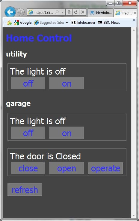
Well, phase 2 of my project is done. The Netduino Plus controls my garage door and lighting. I can query and control them over the network.
The UI is currently a simple web interface served entirely from the Netduino. XML is transformed to HTML via XSLT in the browser, or done on the device if using the Android browser.
Next step is an Android application for a slicker presentation.
#11
Frank
-

- Members
-
- 62 posts
Advanced Member
- LocationNorth Waterboro Maine
Posted 01 December 2010 - 01:38 AM
Fred,
Are you going to release any of your code so others can see how you did this ?
Retired -stone sculptor -macro photographer- novice but avid Go player - Geek
#12
gedw99
-

- Members
-
- 2 posts
New Member
Posted 02 January 2011 - 04:22 AM
I am an Architect and have done a few wireless systems using different hardware etc.
I think at the end of the day thats its allot cheaper and better to put all the wireless to wired interfaceing equipment in the fusebox.
Then everything else in th house is just normal wiring.
Eltako is a german comapny i use that has great stuff. Really
Basically it allows you to interface to your fusebox and control things.
Now the ONLY issue with this of course is that the things you are trying to control might be on a circuit that other things are on.
For me this is not an issue because these are all new builds and so we pull through what we need to control all the way back to the fusebox.
SO what is the other option ?
There is a wireless protcol that does NOT require batteries in the sensor devices.
Its cheap too and very easy to use, compared to zigbee and the others.
http://www.eltako.co...al-freedom.html
Anyway let me knwo if you interested in this. I started to write allot of code to talk to these devices in c#
- Michel Trahan likes this
#13
Charles
-

- Members
-
- 192 posts
Advanced Member
Posted 02 January 2011 - 04:59 PM
PM me when you start getting to the RFID part - I can give you some pointers in the ID-xx incorporation.
#14
Fred
-
- Members
-
- 302 posts
Advanced Member
- LocationUK
Posted 03 January 2011 - 12:45 PM
Thanks for the offer, Charles. I've got an ID-20 reader and played around with that without a problem. I think the bigger (and first) part will be locking and unlocking the door. It's not the sort of door where I can use the normal electric strike plate method. Tehn it'll be a case of campatability with my work system and a friend's place. No point having different fobs for everything.
#15
Fred
-
- Members
-
- 302 posts
Advanced Member
- LocationUK
Posted 03 January 2011 - 01:03 PM
Thought I'd post a picture of the current system in-place. Sorry about the poor camera phone quality. And better though, and you might be able to see my low-quality soldering.
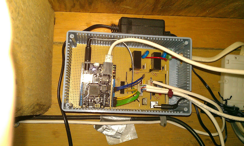
What you can see is:
Top right: Two relays operating mains fluorescent lighting. The blue discs are varistors, as I had problems with the relay contacts being welded together from the kickback when switching the light off.
Bottom right: Smaller relay for operating the garage door. (Hidden behind wiring). 9v voltage regulator to be nice to the Netduino Plus. The supply coming in is 12V but I wanted to isolate the ND from and disturbance caused by the relays.
Bottom middle: An quad optoisolator so I can pick up a 32V signal I found poking around with the "door open" and "door closed" switches inside the garage door opener. Lucky it was a quad. I only needed 2 but manage to blow 2 of the internal LEDs by forgetting the series resistor. Oh well - that what isolation is for I suppose! Blow up something cheap.
The 4-way connector on the right is to the garage door opener. The 10-way is to the light switches. I've used CAT5 cable just because I had a reel lying around. Ovbiously the CAT5 to the Netduino is my home network.
I've currently knocked up a very simple web UI (served up entirely by the Netduino Plus) but will be knocking up a nicer Android UI next.
I'd be interested in seeing how everyone else does their "finished product". I went for a stripboard and used .1" headers soldered onto the end of wires to connect to the Netduino. I think it's too much of a work in progress to etch a PCB. It'll never be more than a one-off so definitley not worth getting something made for me. I did consider using a protoshield to connect to the ND, but it just seemed right that the Netduino should be on top! Maybe .1" headers on top of the board and the ND mounted upside down might be neater? The next version could look quite different.
#16
WannaFly
-

- Members
-
- 17 posts
Member
Posted 04 January 2011 - 01:31 AM
WOW. Fred, thanks for the pictures and descriptions - they are great. As a beginner I've often searched for more complete/finished looking projects wondering if i'll ever do something like this with mine. Yours is definitely a good example! I only have more "temporary" projects planned for my netduino yet  Good job and keep up the good work!
Good job and keep up the good work!
#17
darkSol
-

- Members
-
- 13 posts
Member
Posted 04 January 2011 - 03:16 PM
Great job Fred!
How are you handling the Netduino cycling outputs high and low on startup?
Does it not trigger the garage door relay - or are you using two digital outputs for the relay so that it triggers only when one is high and the other is low?
Can you post schematics?
Thanks!
-David
#18
Fred
-
- Members
-
- 302 posts
Advanced Member
- LocationUK
Posted 04 January 2011 - 04:32 PM
The Netduino starting with outputs high was an issue but solved fairly simply by having a pull down resistor on the output which won the tug-of-war with the internal pull-up one. It's a bit crude but worked well. I looked at using a PNP transistor and driving the output low to activate the relay, but the 3.3V high Netduino output was still seen as low in reference to the 12V used by the rest of the circuitry.
I'll post schematic when I get a chance, and source code. To be honest the most interesting part of the source code is the web server stuff I've already posted. Everything else is fairly simple button handling and constructing XML/HTML strings to send back to the client.
#19
Chris Walker
-

- Moderators
-

- 7767 posts
Secret Labs Staff
- LocationNew York, NY
Posted 04 January 2011 - 09:14 PM
How are you handling the Netduino cycling outputs high and low on startup?
We should probably start a new thread on this, but is the Netduino really cycling outputs high and low on startup? Or is it just setting all the pins to weak-pullup inputs on startup?
If the firmware is cycling outputs high and low on startup, I can put in a ticket to see why...
Chris
#20
Fred
-
- Members
-
- 302 posts
Advanced Member
- LocationUK
Posted 04 January 2011 - 10:10 PM
It's not cycling the outputs, but whilst starting up and before the user code creates the output port the weak pullup inputs are enough to be seen as high if connected to the base of an NPN transistor.
In my case it meant that on start up (e.g. after so power cut) my lights would flash on and my garage door would open.


0 user(s) are reading this topic
0 members, 0 guests, 0 anonymous users


