hey, my lack of experience in the differences in ttl vs rs232 led me here. i also assumed that although the com2 says rs232 i had assumed that i would use it just like com1, and i was wrong. am i also wrong to assume that i could just attach a MAX 232 onto the 1-4 pins and have my appropriate TTL tx and rx? i am working on a board that uses the mini and the xbee (with power regulator for 3.3v). my plan is to make a board that is about the size of the netduino plus but already has the xbee on the board so it could do zigbee (or wifi if you had the right xbee module with wifi). would a MAX 232 solve my problem and allow me to use the com2 for communication with the xbee?
Thanks

netduino mini and max232 for com2
Started by contractorwolf, Apr 10 2012 01:28 AM
2 replies to this topic
#2

Nevyn
-

- Members
-

- 1072 posts
Advanced Member
- LocationNorth Yorkshire, UK
Posted 10 April 2012 - 06:23 AM
I have not tried this with XBee's but I have done it with a FTDI cable connected to a PC. I did not use all four signals on COM2, just the Tx and Rx signals. I used one of the sample circuits from the data sheet.hey, my lack of experience in the differences in ttl vs rs232 led me here. i also assumed that although the com2 says rs232 i had assumed that i would use it just like com1, and i was wrong. am i also wrong to assume that i could just attach a MAX 232 onto the 1-4 pins and have my appropriate TTL tx and rx? i am working on a board that uses the mini and the xbee (with power regulator for 3.3v). my plan is to make a board that is about the size of the netduino plus but already has the xbee on the board so it could do zigbee (or wifi if you had the right xbee module with wifi). would a MAX 232 solve my problem and allow me to use the com2 for communication with the xbee?
Thanks
Do you have details on how you have wired this up to the Mini?
regards,
Mark
To be or not to be = 0xFF
Blogging about Netduino, .NET, STM8S and STM32 and generally waffling on about life
Follow @nevynuk on Twitter
#3
contractorwolf
-
- Members
-
- 23 posts
Member
Posted 16 April 2012 - 03:07 AM
Mark,
i did finally figure this out, and it seems to work pretty well, i have the netduino mini connected to the max232 like this:
netduino pin1 (rs232 tx) -> max232 pin13 (rs232 rx)
netduino pin2 (rs232 rx) -> max232 pin14 (rs232 tx)
netduino pin4 (gnd) -> max232 pin15 (gnd)
netduino pin21 (5v) -> max232 pin16 (5v)
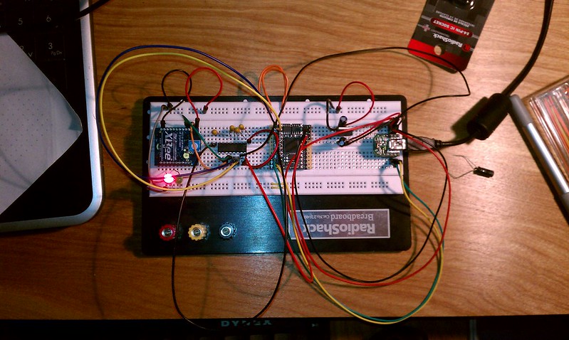
my netduino mini is set to use the COM 1 for debugging (you can see I have an FTDI USB device in the pic below to the right for debugging), what I needed was a way to ALSO use the COM2 for other communication (i.e. xbee)
the max232 also needs a couple of other connections to function, mainly caps on a few pins and some other caps connected to power and gnd (all 1uF from radio shack), I found a great diagram here:

that was from this site:
http://sodoityoursel...evel-converter/
as far as connecting to the xbee, the max 232 connects to the xbee like this:
max232 pin12 (TTL tx)-> xbee pin3 (rx)
max232 pin11 (TTL rx)-> xbee pin2 (tx)
other pins on xbee that must be connected:
xbee pin10 -> GND
xbee pin 1 -> 3.3v (from voltage regulator)
you must note though that the xbee IS NOT A 5v device! so if you are connecting using the 5v power from the netduino mini you must pass through a 3.3v voltage regulator, this will drop the 5V to the 3.3v that the xbee needs. the voltage regulator has just 3 pins, mine were GND, output (3.3v), and input (5v). i also put a 10uF cap between the + and the GND on both sides to filter out the ripples. i am sure most of you guys already know all of this stuff but i just wanted to be complete for anyone who is trying this for the first time.
in code, i just access it like this:
i also want to say that i def wouldnt have been able to figure some of this stuff out without my handy Saleae Logic Analyzer. i would have been guessing about whether or not these chips were even talking if i couldnt just plug in and see exactly what they were saying to each other. I will post drawings and photo of this whole setup tomorrow.
i did finally figure this out, and it seems to work pretty well, i have the netduino mini connected to the max232 like this:
netduino pin1 (rs232 tx) -> max232 pin13 (rs232 rx)
netduino pin2 (rs232 rx) -> max232 pin14 (rs232 tx)
netduino pin4 (gnd) -> max232 pin15 (gnd)
netduino pin21 (5v) -> max232 pin16 (5v)
my netduino mini is set to use the COM 1 for debugging (you can see I have an FTDI USB device in the pic below to the right for debugging), what I needed was a way to ALSO use the COM2 for other communication (i.e. xbee)
the max232 also needs a couple of other connections to function, mainly caps on a few pins and some other caps connected to power and gnd (all 1uF from radio shack), I found a great diagram here:
that was from this site:
http://sodoityoursel...evel-converter/
as far as connecting to the xbee, the max 232 connects to the xbee like this:
max232 pin12 (TTL tx)-> xbee pin3 (rx)
max232 pin11 (TTL rx)-> xbee pin2 (tx)
other pins on xbee that must be connected:
xbee pin10 -> GND
xbee pin 1 -> 3.3v (from voltage regulator)
you must note though that the xbee IS NOT A 5v device! so if you are connecting using the 5v power from the netduino mini you must pass through a 3.3v voltage regulator, this will drop the 5V to the 3.3v that the xbee needs. the voltage regulator has just 3 pins, mine were GND, output (3.3v), and input (5v). i also put a 10uF cap between the + and the GND on both sides to filter out the ripples. i am sure most of you guys already know all of this stuff but i just wanted to be complete for anyone who is trying this for the first time.
in code, i just access it like this:
//this below wouldnt go all in one place but you get the idea
SerialPort xbee = new SerialPort("COM2", 57600);//my xbee is set to 57600

if (!xbee.IsOpen){xbee.Open();}

byte[] buffer = Encoding.UTF8.GetBytes("message to send to xbee");

xbee.Write(buffer, 0, buffer.Length);
i also want to say that i def wouldnt have been able to figure some of this stuff out without my handy Saleae Logic Analyzer. i would have been guessing about whether or not these chips were even talking if i couldnt just plug in and see exactly what they were saying to each other. I will post drawings and photo of this whole setup tomorrow.


0 user(s) are reading this topic
0 members, 0 guests, 0 anonymous users


