Dear all,
I have the beam load sensor which is on the picture. It has 4 cables:
red - E+
white - S-
black - S+
yellow - E-
Can anybody please tell me the proper way to connect it to the netduino? I guess I have to connect Excitation to 3.3V of the netduino and ground...and then E+ and E- to two analog inputs of the netduino and measure the difference of the reading between these two inputs. Is it correct?
Please help me.
Check the image of my beam load sensor -> http://flic.kr/p/9foZj8
Thank you!

Connecting a beam load sensor to netduino
Started by Asaak, Feb 03 2011 09:40 PM
21 replies to this topic
#2

Quiche31
-

- Members
-

- 87 posts
Advanced Member
- LocationFrance
Posted 03 February 2011 - 11:38 PM
Can you post a link to the datasheet of this sensor? The photo does not help muchI have the beam load sensor which is on the picture. It has 4 cables:
red - E+
white - S-
black - S+
yellow - E-
#3
iceman1979
-

- Members
-
- 9 posts
New Member
Posted 04 February 2011 - 01:35 AM
Most of the load cells I've worked with read in the mV. Hook up power to E- and E+ and then read the voltage from S- and S+, you should see the voltage is in the mV range.
You will need a voltage amp circuit to get the voltage up in the 0-3 volt range. I use a INA128 to bring up the voltage and set the gain with a pot. Once you have the voltage up in the 0-3v range you just connect the positive output from the amp to an analog pin on the netduino and read the pin. Once you can read the pin, you can use some known weights to help calculate any weight.
Hope that helps.
#4
Asaak
-
- Members
-
- 26 posts
Member
Posted 04 February 2011 - 06:50 AM
Quiche31 I don't know the ref number of the sensor so I cannot put a datasheet. However, iceman1979 is right, this kind o sensors works this way. The thing is there is no amp on the scale's circuit where the sensor was installed. Just an I2C eeprom ( I guess it was to manage the lcd of the scale...) and a 7130a1, which is som kind of voltage regulator. The rest of the circuit board are just resistors and passive components.
Anyway, so once I want to measure i just have to connect S+ to a pin and S- to the pin called Aref??
thank you
#5
Jan Olof
-

- Members
-
- 41 posts
Advanced Member
- LocationSweden
Posted 04 February 2011 - 09:03 AM
Hi
Aref is the reference voltage normally connected to 3.3V.
On the A version of the boards you had to have an external jumper, on the B version boards
it is default internally jumpered.
/Jan Olof
#6
Asaak
-
- Members
-
- 26 posts
Member
Posted 04 February 2011 - 10:34 AM
So, if I am not wrong, I have to connect S- to ground pin on netduino?
Thanks for the help!
#7
Asaak
-
- Members
-
- 26 posts
Member
Posted 04 February 2011 - 02:33 PM
My apologies if I ask to much but, can somebody show me an example of circuit using the amplifier suggested for example...I am new to this world and I am checking pdf's of INA125 and INA128/129 and I am kind of lost.
Thank you very much!
#8
iceman1979
-
- Members
-
- 9 posts
New Member
Posted 05 February 2011 - 02:37 AM
Not a problem. I was lost too when I started trying to figure out load cells.
This is the IC that I have INA128P. Look at the schematic on the first page.
1. Connect S- to pin 2 of the INA128, connect S+ to pin 3 of the INA128.
2. If you have a bread board connect the netduino +5v and ground pin to the power rails on the bread board.
3. Connect E- and E+ to the breadboards power rails.
4. Connect pin 7 on the INA128 to the +5v rail.
5. Connect pin 4 and pin 5 of the INA128 to the ground rail.
6. Either use a resistor for the gain you want or do what I did and use a pot as a variable resistor. Use a multi meter to determine which two pins of the pot will show a resistance change when you turn the pot and connect those to pins 1 and 8 of the INA128.
7. Connect pin 6 of the INA128 to the analog pin of the netduino.
This should get you up and running quickly.
Back in September of 2007 I took apart a bathroom scale and found some 3 wire load cells. Here is the thread on Electro-tech-online.com where I stumbled through figuring out load cells.
Here is a picture of the load cell I picked up last year and got working with an arduino.
Hope that helps and let me know if you have any more questions on getting this going. I remember it being a pain when I started learing about load cells so if I can help save you some of that heartache I'd be more than happy to.
Thanks
John
- Rob Brinkworth likes this
#10
Asaak
-
- Members
-
- 26 posts
Member
Posted 06 February 2011 - 11:11 AM
Thank you all!!! I've tried to find the component you suggested ( INA128P ) around my city but I couldn't find it. As soon as I get it I would try it and post the results!!
#11
iceman1979
-
- Members
-
- 9 posts
New Member
Posted 06 February 2011 - 05:37 PM
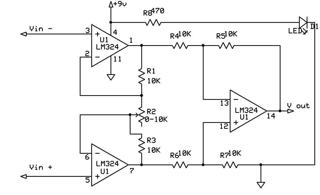
The INA128 is the simplest setup to get going but you can do it with some op-amps and some resistors. My first circuit was done with the LM324 from radioshack. If you have a look at this schematic from my thread on electro-tech-online you can see how to use 3 of the op-amps from the LM324 to make the amplifier. The resistors, pot, and LM324 can all be picked up from radioshack if you want to get something going right away.
#12
Asaak
-
- Members
-
- 26 posts
Member
Posted 15 February 2011 - 06:12 PM
Well I finally got my ina128P and build the installation exactly as iceman1979 kindly described. However I am having a problem. Measuring the mV from the chip output I get 83 mV ( without any weight on it). Then, I need to put a considerable weight until I start to see a change on the mV measured at pin number 5. For example, the original scale with this sensor was able to measure 1,2,3.... grams. Now, it does nothing with measures like 200 or 300 grams. Not until I put a certain weight it starts to measure it and increase proportionally to the applied force. What am I doing wrong?
I am using a gain resistor of 68 Ohms.
The code is this:
and I call the method like this:
and this is an image of the mounted system:
http://flic.kr/p/9irbH2
http://flic.kr/p/9ircva
Thank you!
I am using a gain resistor of 68 Ohms.
The code is this:
    class Bascula
    {

        float tara;
        int voltatge_referencia;
        int resolucio_CAD;
        AnalogInput sensor_pes;
        int max_num_tares;

        public Bascula()
        {
            sensor_pes = new AnalogInput(Pins.GPIO_PIN_A5);
            voltatge_referencia = 3300; //reference voltage of AD in mV
            resolucio_CAD = 1023; //AD resolution
            tara = 0;
        }

        public double GetmV()
        {
            return (((sensor_pes.Read()) * voltatge_referencia) / resolucio_CAD);
        }


    }
and I call the method like this:
    Bascula bascula = new Bascula();

    while (true)
    {
    Debug.Print(bascula.GetmV().ToString() + "mV");
    Thread.sleep(100);
    }
and this is an image of the mounted system:
http://flic.kr/p/9irbH2
http://flic.kr/p/9ircva
Thank you!
#13
iceman1979
-
- Members
-
- 9 posts
New Member
Posted 15 February 2011 - 08:56 PM
Well I finally got my ina128P and build the installation exactly as iceman1979 kindly described. However I am having a problem. Measuring the mV from the chip output I get 83 mV ( without any weight on it). Then, I need to put a considerable weight until I start to see a change on the mV measured at pin number 5. For example, the original scale with this sensor was able to measure 1,2,3.... grams. Now, it does nothing with measures like 200 or 300 grams. Not until I put a certain weight it starts to measure it and increase proportionally to the applied force. What am I doing wrong?
I am using a gain resistor of 68 Ohms.
The code is this:
    class Bascula
    {

        float tara;
        int voltatge_referencia;
        int resolucio_CAD;
        AnalogInput sensor_pes;
        int max_num_tares;

        public Bascula()
        {
            sensor_pes = new AnalogInput(Pins.GPIO_PIN_A5);
            voltatge_referencia = 3300; //reference voltage of AD in mV
            resolucio_CAD = 1023; //AD resolution
            tara = 0;
        }

        public double GetmV()
        {
            return (((sensor_pes.Read()) * voltatge_referencia) / resolucio_CAD);
        }


    }
and I call the method like this:
    Bascula bascula = new Bascula();

    while (true)
    {
    Debug.Print(bascula.GetmV().ToString() + "mV");
    Thread.sleep(100);
    }
and this is an image of the mounted system:
http://flic.kr/p/9irbH2
http://flic.kr/p/9ircva
Thank you!
With a 68ohm resistor your gain should be between 500 - 1000 to 1. Your voltage should be in the V not mv. I used a pot instead of a resistor so that I could play around with the gain. Use a volt meter to test the circuit before trying to implement into the netduino. This will allow you to fine tune the gain so that you get the max resolution. The idea here is to get the voltage swing to be between 0-5v. Having the voltage got to min and max will give you the best resolution when you hook it up to the netduino.
Hope that helps.
John
#14
Asaak
-
- Members
-
- 26 posts
Member
Posted 15 February 2011 - 09:11 PM
As far as I understand, the ADC input can only be between 0-3.3V so why do you say it should go between 0-5v? I tested the way I get the voltage using the code with a voltimeter and it was fine so I gues I am getting it right with.
I am not putting a pot because I checked and with it I didn't obtain gain ( with an impedance like 250 ohms I didn't get any changes in the output of the circuit. )
I am a bit lost..what can I do?
#15
Asaak
-
- Members
-
- 26 posts
Member
Posted 16 February 2011 - 06:36 AM
Just to make it more clear, for instance:
if a have something that weights 200 grams it does not recognize it. If a put 1kgrs then I can se how the response in mV goes high and if I add the previous 200 grams to this 1kgr I can see an increment as well. Somehow, with the empty scale I have an output of 87mV which and I need an "offset" of grams to make the sensor start "sensing".
Any ideas??
#16
iceman1979
-
- Members
-
- 9 posts
New Member
Posted 16 February 2011 - 06:36 AM
As far as I understand, the ADC input can only be between 0-3.3V so why do you say it should go between 0-5v? I tested the way I get the voltage using the code with a voltimeter and it was fine so I gues I am getting it right with.
I am not putting a pot because I checked and with it I didn't obtain gain ( with an impedance like 250 ohms I didn't get any changes in the output of the circuit. )
I am a bit lost..what can I do?
If it is 0-3.3v then thats the range you want to see from the amp. if your pot has 3 pins on it two of them will give you the max resistance and the other two connected will give you a variable resistance that changes as you turn the pot. These two pins on the pot would be the ones you want to connect to.
#17
iceman1979
-
- Members
-
- 9 posts
New Member
Posted 16 February 2011 - 06:42 AM
Just to make it more clear, for instance:
if a have something that weights 200 grams it does not recognize it. If a put 1kgrs then I can se how the response in mV goes high and if I add the previous 200 grams to this 1kgr I can see an increment as well. Somehow, with the empty scale I have an output of 87mV which and I need an "offset" of grams to make the sensor start "sensing".
Any ideas??
yeah, your gain isn't high enough to show the small changes in weight being added. If the gain is set right a small change will be reflected as a large change in voltage.
#18
iceman1979
-
- Members
-
- 9 posts
New Member
Posted 17 February 2011 - 05:58 PM
When I had my amp setup with no weight on the load cell I had it reading out 1v applying light pressure with my thumb I could see the mV going up and down. I had to press hard to get it over 3v but I was only able to get there by playing around with the gain. that's where having a variable resistor helped a lot.
The reason you want it to go from 0 - 3.3v is because of the ADC resolution. The 10bit ADC returns a number between 0 - 1023 which is 1,024 steps it can report for a change in voltage between 0 - 3.3v. So, take 3300mV / 1024 and you get 3.22mV per step. That means that for every 3.22 mV change in voltage your ADC will change by 1. For 87mV you should be seeing a number around 27 in the netduino.
Even though you can't see it the change is happening even when light pressure is applied. If the volt meter can only show down to 1 whole mV then you are missing the changes in voltage down in the decimal range. For instance... 87.000mV and 87.999mV would be seen as 87mV and you would miss the .1 - .9 change that took place. now, if you multiply that 87mv by 10 you get 870mV and the change in .1 - .9 would be seen as 871 - 879. Now that .1 - .9mV change that didn't register on the ADC because it wasn't a change greater then 3.22mV now shows up because the change is 0 - 9mV. This would cause the ADC value to change by about 3 points.
Hope that helps.
John
#19
Asaak
-
- Members
-
- 26 posts
Member
Posted 20 February 2011 - 07:12 PM
I'm sorry, maybe I didn't made myself clear.
You are right when you say that with no load on the sensor I get a reading of 87mV, around 24-27 if we talk in terms of steps of ADC from 0 to 1024.
The problem is in the low weight...for instance, until I don't put a considerable weight I can't see the increase of mV/ADC steps. Then it seems to work fine even with low weight.
Imagine:
I amb not able to measure 100 grams alone...but If I put 1 kgr and check the reading, if I put then this 100 grams I can see the value of mV/ADC steps increasing. I haven't tried with a variable resistor yet but I guess what you want me to do is to reduce the impedance so I will get more gain right? ( right now I am working with a 68 Ohm resistor ).
Thank you!
#20
Asaak
-
- Members
-
- 26 posts
Member
Posted 23 February 2011 - 06:03 PM
I found what was going on! Instead of connecting VREF to ground as suggested, I have to put a voltage in there, like for example, 1V. Then it works fine! ( Readings are not really stable but I am working on that. However, I would really appreciatte any help if someone knows how to stabilize a reading using hardware/software ).
Thank you!


0 user(s) are reading this topic
0 members, 0 guests, 0 anonymous users


