The Netduino forums have been replaced by new forums at community.wildernesslabs.co.
This site has been preserved for archival purposes only
and the ability to make new accounts or posts has been turned off.
Controlling 2WD Chassis using Motor Driver 1A Dual TB6612FNG
Your suggestion above worked so I investigated the code a bit further. The problem was the PWM code. See all the examples I found, PWMA was connected to pin5, So we were choosing channel5, So basically we physically connected it to pin5 to the N+2 but in code you have to choose PIN0. I think this is because I am using 4.3.1.0. The code below works
Thanks everybody for your help.
using System.Threading;
using Microsoft.SPOT;
using Microsoft.SPOT.Hardware;
using SecretLabs.NETMF.Hardware;
using SecretLabs.NETMF.Hardware.Netduino;

namespace MotorController
{
    public class Program
    {
        public static void Main()
        {
            OutputPort stby = new OutputPort(Pins.GPIO_PIN_D0, true);

            //motorA
            PWM motorA = new PWM(Cpu.PWMChannel.PWM_0, 10000, 1, true);
            OutputPort a1 = new OutputPort(Pins.GPIO_PIN_D1, false);
            OutputPort a2 = new OutputPort(Pins.GPIO_PIN_D2, false);
            motorA.Start();

            //motorB
            PWM motorB = new PWM(Cpu.PWMChannel.PWM_1, 10000, 1, true);
            OutputPort b1 = new OutputPort(Pins.GPIO_PIN_D8, false);
            OutputPort b2 = new OutputPort(Pins.GPIO_PIN_D9, false);
            motorB.Start();


            while (true)
            {
                //this controls motorA
                a1.Write(false);
                a2.Write(true);
                motorA.DutyCycle = (double)0.7;

                //this controls motorB
                b1.Write(false);
                b2.Write(true);
                motorB.DutyCycle = (double)0.7;
             }
        }
    }
}
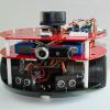
I have done some minimal work on the Netduino for our company and it was so interesting, I decided to order 1 for myself with a few extra components and try to build a simple 2WD robot that I can control using my android phone over Bluetooth. I got the Bluetooth parts working with my PC to test. I will code the android stuff at a later stage using Xamarin Android.
The Problem I am having is controlling the 2 motors. I will post my poor attempt of code below. I found a few examples online but I could not get any of them to work. I am running firmware version 4.3.1.0. So I think the reason some of the examples do not work for me is because they are using an older version of the framework. I tried a cool library I found on codeplex, the link http://uplibrary.codeplex.com/
I tried to this to work but I was not so lucky. I tried a few breakpoints and nothing seems to break but the motors will not turn, they just refuse to turn
The Components :
1 x Netduino Plus 2
1 x Bluetooth Device (Got this working well with my PC and Netduino, used a framework called 32feet.Net)
TB6612FNG breakout to motors AO1 = Red motor lead (Right) AO2 = Black motor lead (Right) BO2 = Black motor lead (Left) BO1 = Red motor lead (Left)
using System;
using System.Net;
using System.Net.Sockets;
using System.Threading;
using Microsoft.SPOT;
using Microsoft.SPOT.Hardware;
using SecretLabs.NETMF.Hardware;
using SecretLabs.NETMF.Hardware.Netduino;

namespace MotorController
{
    public class Program
    {
        public static void Main()
        {

            OutputPort stby = new OutputPort(Pins.GPIO_PIN_D0, true);
            TB6612FNG motors = new TB6612FNG(Cpu.Pin.GPIO_Pin1, Cpu.Pin.GPIO_Pin2, Cpu.PWMChannel.PWM_5);
            motors.MotorModeA = MotorMode.CW;
            motors.MotorSpeedA = 50;  // Set the motor to 50% speed

            while (true)
            {
                motors.MotorModeA = MotorMode.CW;
                motors.MotorSpeedA = 50;  // Set the motor to 50% speed
            }

        }

    }
}
Wild guess since I do not have any of the pieces, but I suspect changing the motor mode and speed over and over again as fast as possible might have unintended consequences.
Try setting them both, sleep 1 second then set speed to 0; get rid of the while loop. If that works you need to rethink your logic.
using System;
using System.Net;
using System.Net.Sockets;
using System.Threading;
using Microsoft.SPOT;
using Microsoft.SPOT.Hardware;
using SecretLabs.NETMF.Hardware;
using SecretLabs.NETMF.Hardware.Netduino;

namespace MotorController
{
    public class Program
    {
        public static void Main()
        {

            OutputPort stby = new OutputPort(Pins.GPIO_PIN_D0, true);
            TB6612FNG motors = new TB6612FNG(Cpu.Pin.GPIO_Pin2, Cpu.Pin.GPIO_Pin3, Cpu.PWMChannel.PWM_5);
            motors.MotorModeA = MotorMode.CW;
            motors.MotorSpeedA = 1;
            Thread.Sleep(2000);
            motors.MotorSpeedA = 2;
            Thread.Sleep(2000);
            motors.MotorSpeedA = 4;
            Thread.Sleep(2000);
            motors.MotorSpeedA = 6;
            Thread.Sleep(2000);
            motors.MotorSpeedA = 8;

            //while (true)
            //{
            //    motors.MotorModeA = MotorMode.CW;
            //    motors.MotorSpeedA = 50;  // Set the motor to 50% speed
            //}

        }

    }
}
Hi Spiked, thanks for the prompt reply, I tried what you said and the motor still does not turn
I just have 1 motor connected for now, If I can get it to work with 1 then I can get it to work with 2. I cant seem to find out why the motors don't turn. Any other advice ?
Heres a link to my wiring, the code above as not changed, Im pretty sure im missing something small. Im not sure what it is. Probably a part of my brain perhaps
The motor driver IC has separate power supply for motors (VM) and logic (VCC). You can use the batteries to power both Netduino and motors (if it is a standard AA battery holder, you should be able to insert a wire between battery and the positive contact lead and solder it to motor board VM input).
That will get you going, but down the road keep in mind there is a reason logic voltage and motor voltage are usually kept apart. There are several ways to accomplish isolation, one the easiest/best being 2 different batteries.
The problem is, in some configurations the motor pull can drop the voltage below what the logic can tolerate, even if just for a microsecond the results can be bad. Also motors, being mechanically/electrically connected (brushes sparking) tend to introduce 'noise' on the circuit and cause all kinds of hard to find problems.
Again, hook it up as you described, see if it works, then think a more permanent solution.
using System;
using System.Net;
using System.Net.Sockets;
using System.Threading;
using Microsoft.SPOT;
using Microsoft.SPOT.Hardware;
using SecretLabs.NETMF.Hardware;
using SecretLabs.NETMF.Hardware.Netduino;

namespace MotorController
{
    public class Program
    {
        public static void Main()
        {

            OutputPort stby = new OutputPort(Pins.GPIO_PIN_D0, false);
            TB6612FNG motors = new TB6612FNG(Cpu.Pin.GPIO_Pin1, Cpu.Pin.GPIO_Pin2, Cpu.PWMChannel.PWM_5);
            motors.MotorModeA = MotorMode.CW;
            motors.MotorSpeedA = 60;
            Thread.Sleep(100000);
        }

    }
}
I tried taking the power directly from the 4 AA batteries and connected 1 end to VM and the other to GND and it still does not work. When I measure VM and GND I get 3v, so now there is power going to the motors. Is there anything else I can try ? I mean instead of connecting a Motor, Can I connect an LED to A01 and A02 and pulse the LED. just so we know the hardware is working correctly, there must be an easier way to debug this. if I connect the motors directly to the battery they turn quite fast, so I know the motors are working.
Well, it does not seem right to have VM = 3V for 4 AA batteries, it should be around 6V (4*1.5V) for regular alkaline or 4.8 (4*1.2V) for NiMH cells. Where have you soldered the wire on the battery holder? 3V would mean you are using only two batteries, i.e. wrong terminal.
And it talks about the StandBy Pin. Could that be my problem ? Im not sure. I did set it to true and ran the program, did nothing, I set it to false and it didnt do anything. So im not entirely sure.
I have checked the datasheet again and I think there is a problem with control signal voltage levels: if you power the motor control board by 5 - 6 V, the Netduino 3.3V outputs do not have high enough voltage (VIH = 0.7*VCC = 0.7*5 = 3.5V).
So, connect VCC to Netduino 3.3V, STBY to 3.3V, VM to 5-6V.
To manually test the motors, connect PWM to 3.3V and then either IN1 or IN2 to 3.3V.
Your suggestion above worked so I investigated the code a bit further. The problem was the PWM code. See all the examples I found, PWMA was connected to pin5, So we were choosing channel5, So basically we physically connected it to pin5 to the N+2 but in code you have to choose PIN0. I think this is because I am using 4.3.1.0. The code below works
Thanks everybody for your help.
using System.Threading;
using Microsoft.SPOT;
using Microsoft.SPOT.Hardware;
using SecretLabs.NETMF.Hardware;
using SecretLabs.NETMF.Hardware.Netduino;

namespace MotorController
{
    public class Program
    {
        public static void Main()
        {
            OutputPort stby = new OutputPort(Pins.GPIO_PIN_D0, true);

            //motorA
            PWM motorA = new PWM(Cpu.PWMChannel.PWM_0, 10000, 1, true);
            OutputPort a1 = new OutputPort(Pins.GPIO_PIN_D1, false);
            OutputPort a2 = new OutputPort(Pins.GPIO_PIN_D2, false);
            motorA.Start();

            //motorB
            PWM motorB = new PWM(Cpu.PWMChannel.PWM_1, 10000, 1, true);
            OutputPort b1 = new OutputPort(Pins.GPIO_PIN_D8, false);
            OutputPort b2 = new OutputPort(Pins.GPIO_PIN_D9, false);
            motorB.Start();


            while (true)
            {
                //this controls motorA
                a1.Write(false);
                a2.Write(true);
                motorA.DutyCycle = (double)0.7;

                //this controls motorB
                b1.Write(false);
                b2.Write(true);
                motorB.DutyCycle = (double)0.7;
             }
        }
    }
}


![Cannot find any entrypoint! - The program '[16] Micro Framework application: Managed' has exited with code 0 (0x0). - last post by Sukasa](http://www.gravatar.com/avatar/1b70a4a9eb6d1251337a00052a6fc5e0?s=100&d=http%3A%2F%2Fforums.netduino.com%2Fpublic%2Fstyle_images%2Fmaster%2Fprofile%2Fdefault_large.png)


