This is for my Netduino Plus, but I assume that it's equally applicable to the Netduino.
I purchased a quad thermocouple shield from McLaughlin Engineering (http://store.ryanjmc...-products/giyx3). The arduino sample on github implies that you just have to clock the shield, and you will be able to read back the temperature data. However, the Netduino SPI library / wiki says that you have to write to the device before reading.
Can anyone explain to me why this is the case, and if it's possible to work around it somehow? When I get the board, I will try writing 0s to it and hope for the best, but at the moment I'm just stubbing out code while I wait for my shield to arrive.

Why does the SPI library only have WriteRead()?
Started by Dave M., Nov 03 2011 09:14 PM
14 replies to this topic
#2
?: post #2")
Stefan
-

- Members
-

- 1965 posts
Moderator
- LocationBreda, the Netherlands
Posted 03 November 2011 - 09:41 PM
SPI works with a clock, see it as a heart.
On every heartbeat, the SPI device can send and/or receive data. The heartbeat is driven by the SPI Master, in this case the Netduino. The amount of heartbeats determines how much data the SPI Slave sends to the netduino. So by writing data, the Netduino sends out a heartbeat. At the same time, the SPI Slave sends the same amount of data back.
It's quite regular to send just 0-bytes, but the SPI Master always decides how many bytes it will receive by sending bytes.
I worked around this in a class I wrote, which also has just a Read() method. You need to specify the amount of bytes to read though. On the background it creates an empty write buffer 
"Fact that I'm a moderator doesn't make me an expert in things." Stefan, the eternal newb!
My .NETMF projects: .NETMF Toolbox / Gadgeteer Light / Some PCB designs
My .NETMF projects: .NETMF Toolbox / Gadgeteer Light / Some PCB designs
#3
Stefan W.
-

- Members
-
- 153 posts
Advanced Member
Posted 03 November 2011 - 11:14 PM
Well, if you don't connect MOSI (the line where you send the data), then it literally does not matter what you send Also, be sure to get the headers for the arduino if you want to use it as a shield, it seems the "shield" does not come with them (so you'd have to solder wires or connectors to them).
Also, be sure to get the headers for the arduino if you want to use it as a shield, it seems the "shield" does not come with them (so you'd have to solder wires or connectors to them).
I believe that no discovery of fact, however trivial, can be wholly useless to the race, and that no trumpeting of falsehood, however virtuous in intent, can be anything but vicious.
-- H.L. Mencken, "What I Believe"
-- H.L. Mencken, "What I Believe"
#4
Dave M.
-
- Members
-
- 53 posts
Advanced Member
Posted 07 November 2011 - 05:50 PM
Ok, thanks guys, I'll give that a shot! I didn't order headers since they were out of stock, but I think I can steal them from one of my other shields that doesn't have them installed yet.
#5
Dave M.
-
- Members
-
- 53 posts
Advanced Member
Posted 22 November 2011 - 06:44 PM
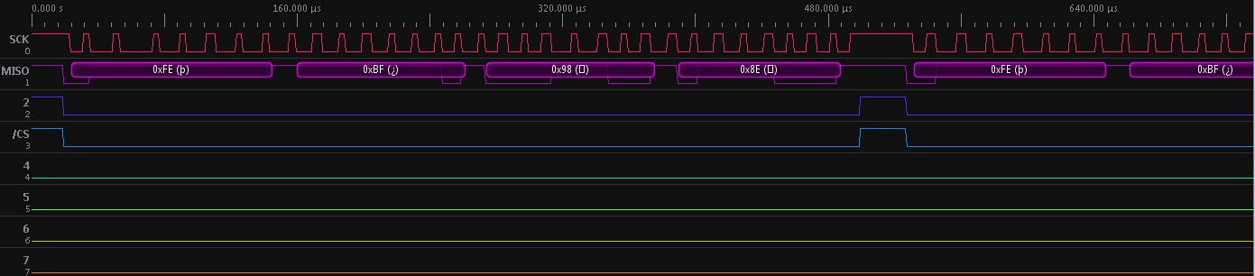
Well, I finally got the headers on and have started testing. I'm not having much luck with the netduino side of things. As a test, I started with the Arduino source that Ryan McLaughlin supplies here. Everything worked fine and although there is a strange temperature offset, the communication works fine. It was also good to run the arduino project to figure out which TCs are connected to which digital I/O pins.
Here's a screenshot from the logic analyzer:
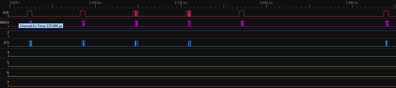
I then moved the shield over to my Netduino and ran my code. I distilled my code down to the following few lines that should read in the data:
Here's what my logic analyzer showed me:
and zoomed in:
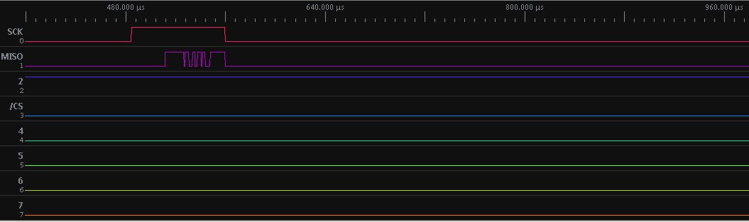
I must have done something dreadfully wrong with WriteRead, but from what I gathered from everyone's suggestions, I should "write" out 4 bytes to read back 4 bytes...
Here's a screenshot from the logic analyzer:
I then moved the shield over to my Netduino and ran my code. I distilled my code down to the following few lines that should read in the data:
while( true) {
    var _spi_config = new Microsoft.SPOT.Hardware.SPI.Configuration( SecretLabs.NETMF.Hardware.NetduinoPlus.Pins.GPIO_PIN_D7, false, 0, 0, true, false, 1000, Microsoft.SPOT.Hardware.SPI.SPI_module.SPI1);
    byte[] outval = new byte[4];
    _spi.WriteRead( new byte[] { 0x00, 0x00, 0x00, 0x00 }, outval);
}
Here's what my logic analyzer showed me:
and zoomed in:
I must have done something dreadfully wrong with WriteRead, but from what I gathered from everyone's suggestions, I should "write" out 4 bytes to read back 4 bytes...
#6
Stefan W.
-
- Members
-
- 153 posts
Advanced Member
Posted 23 November 2011 - 02:05 AM
The image from the logic analyzer looks like you switched the clock and chip select pins.
I believe that no discovery of fact, however trivial, can be wholly useless to the race, and that no trumpeting of falsehood, however virtuous in intent, can be anything but vicious.
-- H.L. Mencken, "What I Believe"
-- H.L. Mencken, "What I Believe"
#7
Dave M.
-
- Members
-
- 53 posts
Advanced Member
Posted 23 November 2011 - 01:29 PM
The image from the logic analyzer looks like you switched the clock and chip select pins.
It looks strange, indeed, but please note that I merely moved the shield from the arduino (working) to the netduino.
The only variable is the SPI code, which makes me think I either didn't initialize the SPI object properly, or
WriteRead() isn't working as expected, either because it's not designed to work the way I need it to, or because
I'm using it incorrectly.
#8
Stefan
-
- Members
-
- 1965 posts
Moderator
- LocationBreda, the Netherlands
Posted 23 November 2011 - 01:37 PM
Try this:
while( true) {
    var _spi_config = new Microsoft.SPOT.Hardware.SPI.Configuration( SecretLabs.NETMF.Hardware.NetduinoPlus.Pins.GPIO_PIN_D7, false, 0, 0, true, false, 1000, Microsoft.SPOT.Hardware.SPI.SPI_module.SPI1);
    byte[] outval = new byte[4];
    _spi.WriteRead( new byte[] { 0x00, 0x00, 0x00, 0x00 }, outval);
}
var _spi_config = new Microsoft.SPOT.Hardware.SPI.Configuration( SecretLabs.NETMF.Hardware.NetduinoPlus.Pins.GPIO_PIN_D7, false, 0, 0, true, false, 1000, Microsoft.SPOT.Hardware.SPI.SPI_module.SPI1);
_spi.config = _spi_config; // Actually loads the SPI config
while( true) {
    byte[] outval = new byte[4];
    _spi.WriteRead( new byte[] { 0x00, 0x00, 0x00, 0x00 }, outval);
}
"Fact that I'm a moderator doesn't make me an expert in things." Stefan, the eternal newb!
My .NETMF projects: .NETMF Toolbox / Gadgeteer Light / Some PCB designs
My .NETMF projects: .NETMF Toolbox / Gadgeteer Light / Some PCB designs
#9
Dave M.
-
- Members
-
- 53 posts
Advanced Member
Posted 23 November 2011 - 02:14 PM
The image from the logic analyzer looks like you switched the clock and chip select pins.
So actually, I didn't look closely enough at the sample arduino code. His library is bitbanging DIO, and not using an SPI library. I assumed too much by looking at SPI-related variables like MISO and SCLK and didn't look deep enough. I have to look at the NETMF SPI info, because the pins actually might be swapped on the board... who knows? I'll be more thorough now and will post up what I find. Thanks for making me think twice about the setup.
#10
Dave M.
-
- Members
-
- 53 posts
Advanced Member
Posted 23 November 2011 - 02:16 PM
Try this:
var _spi_config = new Microsoft.SPOT.Hardware.SPI.Configuration( SecretLabs.NETMF.Hardware.NetduinoPlus.Pins.GPIO_PIN_D7, false, 0, 0, true, false, 1000, Microsoft.SPOT.Hardware.SPI.SPI_module.SPI1);
_spi.config = _spi_config; // Actually loads the SPI config
while( true) {
    byte[] outval = new byte[4];
    _spi.WriteRead( new byte[] { 0x00, 0x00, 0x00, 0x00 }, outval);
}
That's what my "real" code does. When I distilled it for the post, I accidentally reinstantiated the object every time through the loop.
#11
Dave M.
-
- Members
-
- 53 posts
Advanced Member
Posted 23 November 2011 - 02:23 PM
So actually, I didn't look closely enough at the sample arduino code. His library is bitbanging DIO, and not using an SPI library. I assumed too much by looking at SPI-related variables like MISO and SCLK and didn't look deep enough. I have to look at the NETMF SPI info, because the pins actually might be swapped on the board... who knows? I'll be more thorough now and will post up what I find. Thanks for making me think twice about the setup.
Back to the drawing board... the shield library uses the same pins. I will start writing a bitbanging class to deal with shield communication, unless anyone can think of something I'm doing wrong here...
#12
Stefan
-
- Members
-
- 1965 posts
Moderator
- LocationBreda, the Netherlands
Posted 23 November 2011 - 02:46 PM
From http://ryanjmclaughl...Pin_Connections
From Netduino specs (http://www.netduino....duino/specs.htm):
So, with managed SPI, pin 11 is MOSI, pin 12 is MISO and 13 is SCK.
Any other pin (except pin 4 due to a bug) can be used as chip select.
I don't quite understand why it has 4 chip selects though.
Pin Connections
- 13 - SCK
- 12 - SO
- 10 - CS1
- 9 - CS2
- 8 - CS3
- 7 - CS4
- 6 - LED1
From Netduino specs (http://www.netduino....duino/specs.htm):
digital pins 11-13: SPI MOSI, MISO, SPCK
So, with managed SPI, pin 11 is MOSI, pin 12 is MISO and 13 is SCK.
Any other pin (except pin 4 due to a bug) can be used as chip select.
I don't quite understand why it has 4 chip selects though.
"Fact that I'm a moderator doesn't make me an expert in things." Stefan, the eternal newb!
My .NETMF projects: .NETMF Toolbox / Gadgeteer Light / Some PCB designs
My .NETMF projects: .NETMF Toolbox / Gadgeteer Light / Some PCB designs
#13
Dave M.
-
- Members
-
- 53 posts
Advanced Member
Posted 23 November 2011 - 02:50 PM
So, with managed SPI, pin 11 is MOSI, pin 12 is MISO and 13 is SCK.
Any other pin (except pin 4 due to a bug) can be used as chip select.
Yes, this is what I saw as well, so figured the SPI library should have worked.
I don't quite understand why it has 4 chip selects though.
It has four chip selects because the shield has four MAX31855s on it, one for each thermocouple.
#14
Dave M.
-
- Members
-
- 53 posts
Advanced Member
Posted 23 November 2011 - 03:59 PM
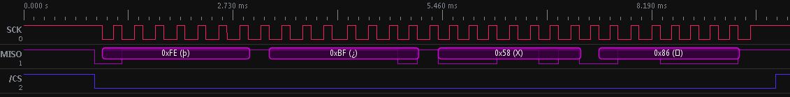
Ok, I ported everything to the netduino using the bitbanging approach, and it seems to be working. My number conversion is a little off, but that's the easy part to fix.
Thanks for the replies, everyone!
I'm not sure if it's useful or not to post this port somewhere (github?), so just let me know if you need / want it.
Thanks for the replies, everyone!
I'm not sure if it's useful or not to post this port somewhere (github?), so just let me know if you need / want it.
#15
Dave M.
-
- Members
-
- 53 posts
Advanced Member
Posted 23 November 2011 - 04:26 PM
And as luck would have it, I've run the Arduino code again to compare temperatures, and now the board doesn't seem to work at all. Yesterday, I would get the cold junction temperature (roughly 25C), even if the TC was disconnected. The serial output indicated that the TC was disconnected, and there weren't shorts to gnd or vcc. Today, I get 0 for CJT, and all of the fault flags are set. Guess I will have to contact the manufacturer now.


0 user(s) are reading this topic
0 members, 0 guests, 0 anonymous users


