The Netduino forums have been replaced by new forums at community.wildernesslabs.co.
This site has been preserved for archival purposes only
and the ability to make new accounts or posts has been turned off.
This is the basic circuit. But I would like to alter the following:
- use a premade USB charger unit like this: sparkfun micro usb charger - Data sheed with schematic here
- add more LEDs: 30 outer ring, 16 inner ring (8 on each side) and 8 for the solo lights with bezel mounts on the inner surface of the disc (4 on each side) = total of 54
- Can I simply smolder the usb charger directly to the netduino and and attach >>both<<??? battaries onto that one charger? If yes can you please clarify how the batteries should be wired/smoldered to the usb charger?
- If I go with 54 LEDs:
- Do I need other batteries? I bought 54 x nichia 6500mcd 45° - data sheet here
- If the batteries stay the same, will my LEDs simply run out of power faster or are they going to shine less bright?
- If they shine less bright, what battery do i need?
Hello Bpkdasbaum.
I don't have much experience about LiPo-charging, but to be honest, I don't like the charging/detecting circuit above.
I am not sure, but it seems that you have to balance the charge when two or more LiPO batteries are connected together. Another clue is that there's no LiPo batteries chargers for series pattern. You find balanced chargers, single-cell chargers, but no double-cell chargers...at least I wasn't able to find them.
Thus, I'd suggest to use a couple of LiPo (3.7V each), but with a limitation (at least in the beginning): to charge the batteries, you must detach them from the circuit and connect to the proper changer, which can be a couple of the Sparkfun USB modules.
When the batteries have to connected to the circuit, they are in series, thus the overall voltage is about 7.5V.
About increasing the number of leds, I guess there's no problem. The MAX chip allows you to connect a large quantity of leds with ease. BTW, there's another problem related to the current flowing in the circuit.
The circuit above is powering the MAX+leds with +5V. This supply is given by the small regulator embedded in the Netduino Mini, and it's *NOT* designed for large powers. It would result in a overheating.
The suggested approach is to feed the +7.5V to the Netduino, thus it gets its own power. Then, *ANOTHER* power supply, just for the leds-stage. Conveniently, this PSU should be a "step-down" DC-DC converter, thus its high efficiency leads to a longer battery duration, and to a lesser thermal energy waste.
Cheers
Biggest fault of Netduino? It runs by electricity.
I don't have much experience about LiPo-charging, but to be honest, I don't like the charging/detecting circuit above.
I am not sure, but it seems that you have to balance the charge when two or more LiPO batteries are connected together. Another clue is that there's no LiPo batteries chargers for series pattern. You find balanced chargers, single-cell chargers, but no double-cell chargers...at least I wasn't able to find them.
Mario, you are very much correct. LiPo batteries *must* be balance charged.
The other thing I would say is if you are charging LiPo batteries, you really should get a "LIPOSACK." Should something go wrong with the batteries, it can mean the difference between some smoke damage in your house and a full on fire.
The other thing I would say is if you are charging LiPo batteries, you really should get a "LIPOSACK." Should something go wrong with the batteries, it can mean the difference between some smoke damage in your house and a full on fire.
I didn't want to talk about the danger about the Lithium batteries, because -as stated- I have no experience enough. However, the Polymer-Lithium (LiPo) should be aware from being explosive, I guess.
Anyway, you are confirming me that it's better to charge them separately.
Cheers
Biggest fault of Netduino? It runs by electricity.
I kind of thought small single cells are safe to use if charged correctly and also wired correctly into a circuit.
I mean the original one worked ... and it was made by guys from this forum. also afaik the newer cellphones all use lipo cells as a battery?
Also, is there an alternative? I mean i went for lipo not only because they were in the original design, but also because they are small and fit into the disk.
The idea is to make the whole disk chargable without taking out the batteries everytime and thus even use it as a decorative lamp at home.
The LiPo should be a lot safer than the normal Lithium batteries. Basically they're protected, thus is much harder that explode.
A single cell gives you 3.7V, thus is not enough to power the Netduino. You must use at least two cells, for a total of about 7.4V. To tell the truth, even 7.5V is just the minimum threshold of usage for the Netduino regulator, thus that's not the best solution.
Well, the most decent solution I may suggest is the following:
use just a LiPo cell (3.7V), with the related chanrger;
add a step-up module (input 3..5V, output 9..12V) to power the Netduino *ONLY*;
power the led set (MAX included) directly using the battery power (no conversion);
The Netduino needs very few energy compared to the leds, and a step-up module has an efficiency of over 60-70%. It means that most of the energy is used for the leds, where there's NO conversion (i.e. power loss) at all.
Hope it helps.
Cheers
Biggest fault of Netduino? It runs by electricity.
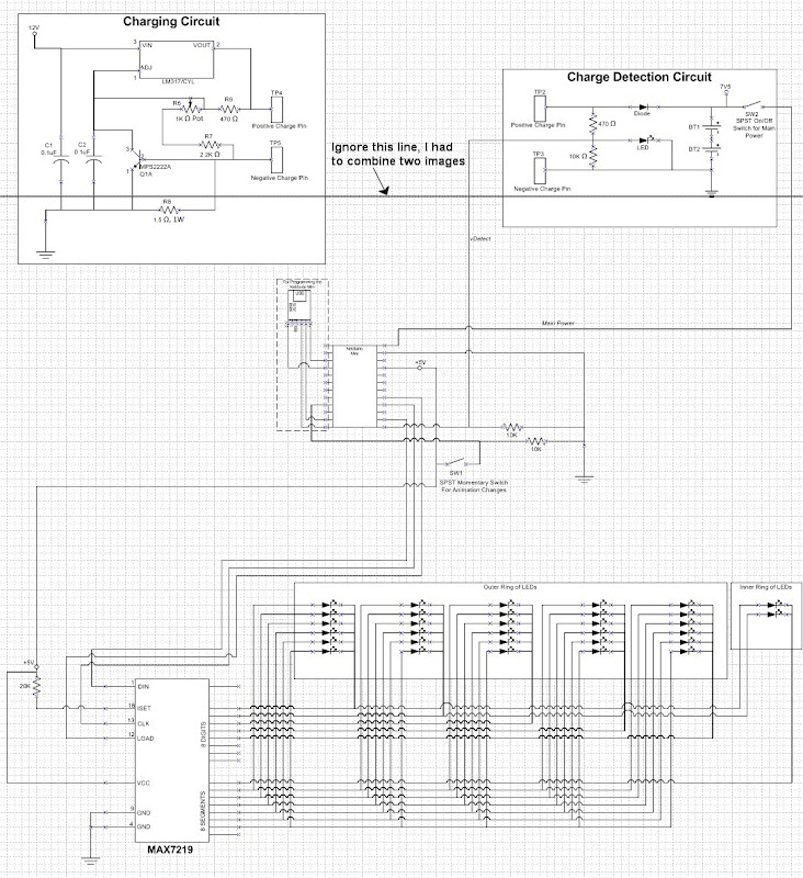
I prepared and new Schematic ... was a pain in the ass to learn how to use a circuit diagram program :E but it was worth it. The Schematic is far from being completed though.
- Don't know how to connect the battery directly to the max and the LEDs O_o? Do I need another Step Up Module for that too? At the moment it looks like it is powered over the netduino with 5V ... or do you mean by "no conversion" that it will run just fine with 3,7 too directly from the battery too?
- Don't know how the step up module will look like. I found a premade version with a build in potetiometer, supposed to be regulating from output 2V-35V and input ... this will take some time to research for me, already had a quick peek at it though. If i understood correctly i can switch the potention meter from 10k ohm to 1k ohm, since i only need to set it up from 3,7 to around 9 volt for easier adjusting
- GND is Ground ... where does this go in the actual setup, do i have to wire it somewhere, if yes where to? Guess this one is total noob question
- Don't know if i copied the wires correnctly going from arduino to the mx7219
. Don't know if I set up the LEDs correntcly, since i added more to the original design, i simply expanded it though, so it should be fine
And in case anyone wants to adjust the schematic and contribute, here is the .sch for Eagle:
== Battery ==
Is it enough a 3.7V/850mAh?...Well, it depends on the usage.
Assuming that:
most of the energy need for the leds: Netduino and MAX(*) itself, suck very little;
*ALL* the battery energy is available for the circuit (high efficiency, no heat waste);
It means that you may *theoretically* suck 850mA continuously for just an hour, or 85mA for 10 hours...so away.
Now, ask yourself: how is the current used for one led? how is the average number of leds enlightened?
It follows the simple calculation...but the experience tells even more.
(*)excluding the led
== Step-up ==
The circuit in the lower-right corner is *NOT* a step-up, but a normal regulator having low-efficiency.
A possible step-up module could be this one.
However, the current available is pretty low (about 100mA), thus *of sure* it cannot used to power the leds.
The actual problem is that the MAX cannot be powered at 3.7V, thus you must power it at 5V along with the Netduino. This would not be a problem, unless the MAX has to power the led set.
== Led power ==
The simplest way to solve the problem above, is to insert some kind of buffer/driver on the MAX's SEGx lines. It has to act as voltage level shifter, from the 5V MAX level to the 3.7V needed for the led.
Let me some time to find out a decent solution, but I think there are no other (simple) way to solve it out...
== GND ==
What's problem about GND?
It's the "ground" wire/plate: the electrical point common for any circuit having a conventional potential of zero Volt.
There are some minor optimization can be made on the whole circuit, but we'll talk about them later.
Cheers
Biggest fault of Netduino? It runs by electricity.
Current 10 mA 20 mA 30 mA
Voltage 3,00 V 3,20 V 3,30 V
light power 3075 mcd 6150 mcd 9225 mcd
So 50x20mA = 1000mA ... meaning i could power the whole disk nonstop for about 45min before recharging. Thats plenty of time. And at home it will be connected to usb anyway the whole time as a lamp near my pc.
== Max7219 ==
I though the whole purpose of the chip was to give the right voltage to the targeted bits/leds? It says on Maxims homepage Only one external resistor is required to set the segment current for all LEDs. So that shouldnt be problem right, since the resistor is alrady set (20k ohm in the original schematic).
But then again, this is only my assumption, with my limited electronics knowledge >_>
Within the original design it looks to me like it is going from two battaries 7.4V to the netduino, then the netduino has its own 5v out going to the max, and the max is set to 3,5V output (thats the volatage of the LED used in the original design) through the resistor at the build in converter or something. My LEDs need only 3,2V, guess I'll need another resistor then?
I'd get a step back to the pair of batteries, thus the overall voltage will be 7.4V.
This seems the most convenient option, because the led need a voltage that is too close to the single cell battery. Moreover, with a single cell battery (i.e. 3.7V) there are the problems mentioned in my previous post.
Let's forget the battery charger for a while.
You should use two batteries in series, and a DC-DC converter like this one. It allows as input a wide range of voltages, and is capable of an output of 1A at +5V.
At this point, you'll use the DC-DC regulated supply for either the Netduino (directly on the +5V pin), and for the MAX, leds included.
With this trick you'll double the total capacity, thus the duration becomes almost twice.
I'll send you a solution for the charger: let me some time to draw it.
Cheers
Biggest fault of Netduino? It runs by electricity.
From what i learned today about charging multi cell lipo batteries, it is possible but dangerous and both batteries need to be checked by the factory to be usable together ... and even then they require a rather complicated charger. Found it here. I have also found some multicell chargers but they are all huge.
Frankly i don't even understand how they made it work in the original design O_o?
== LEDs Voltage ==
I found out how to set the output voltage for the max7219 from the data sheet (table 11). The Resistor (R1 in the schematics) needs to be ~24kohm for 3.2V. Yay \o/ ... So the max takes in 5v from the netduino and passes on 3.2v to the Leds.
I'd get a step back to the pair of batteries, thus the overall voltage will be 7.4V.
This seems the most convenient option, because the led need a voltage that is too close to the single cell battery. Moreover, with a single cell battery (i.e. 3.7V) there are the problems mentioned in my previous post.
Another alternative would be to find a rechargeable battery that has an output of 5V or 9-12V right? Since the netduino can be powered by either. I'll check if I can find something like that.
EDIT: I am wondering how other ppl use their netduino??? can't find anything on power source related problems ... am I the only one who wants a circuit to run through usb and a rechargeable battery like a cellphone ^^??? I thought this technology is quite common now days? Even my PC Mouse is working that way, has a 1.2V rechargable battery, but is chargable via usb which is 5V. Or am i missing something here?
The Lithium (and LiPo) batteries are powerful, but also must managed with care.
A knife would kill a people, but you can't avoid to eat or shaving, because has a blade...
As LadyAda pointed out, the only allowed pattern is to place in series two batteries. Note that this is *NOT* a totally safe pattern, but it would be not even with any other kind of battery.
That's because the two (or more) batteries involved may not be perfectly equal, and their discharge may be different. Even the current flowing thru is exactly the same.
For instance, one of them discharges faster, and the voltage drops are different.
BTW, your car battery (12V) has 6 2V-cells in series, and it's safe...how is it? That's because the whole battery has been made with the same material, same manufacturing, same operator, etc. What would be the difference?
It's much when you take 2 children, and two twins.
Instead, when you take any battery (typically purchased), you have any guarantee that they come from the same lot, same operator, same material, etc.
Under these circumstances, a *VERY GOOD* pattern for a series batteries, is to monitor the total voltage, as long the intermediate voltage. Thus, you may see when a battery is below a certain limit.
...ANYWAY...
I wouldn't be scared...at least, I'd try some experience...
Below is depicted my suggestion.
Consider the bottom section of the scheme. You have two batteries (don't care about the alkaline pair: keep it as a single LiPo-cell), which have:
to be placed in series, when operating;
to be charged separately (independently), when not operating.
to be excluded when you want your circuit switched off;
NOTE the limitation: either operating, or charging.
The breadboard would be the disc circuit.
Your disc will have a 5-holes *female* connector, connected to the batteries and to the circuit (breadboard) as depicted.
Afterward, you will have another TWO *male* 5-pins connectors: one for operating, the second for charging.
When no connector is plugged in, the disc is switched off.
The operating connector has just a couple of wires, as depicted in the upper section of the picture.
If you try to follow the current path, you'll see that the batteries are actually placed in series, thus your circuit is 7.4V powered.
The second "charging" connector is trivial, and must be wired to a couple of simple LiPo chargers. Any kind of charger would fit (accordingly to the battery type).
All the remaining considerations, about the DC-DC to efficiently step down the voltage from 7.4 to 5V, are still valid.
Hope it helps.
Cheers
I was following up on your first post Mario, when you said:
The circuit above is powering the MAX+leds with +5V. This supply is given by the small regulator embedded in the Netduino Mini, and it's *NOT* designed for large powers. It would result in a overheating.
Amd I just found out 2 things:
1. netduino microcontroller max current: 200 mA total
2. USB max current: 500 mA
Since I need 1000 for the LEDs alone 80 something for the netduino and probably another 80 for the max7219, I won't be able to run this thing via USB. Guess my dreams just got shattered :L
So back to square one. No USB charger. Back to two batteries. Will try using the charging and charge detechtion circuit from the original design >_> but add a step down from batteries -> max7219 instead of batteries -> netduino -> max7219 as you already suggested. I will need a step down from 7.4V to 5V then.
I also checked out the charging circuit and it was designed by someone who knows what he is doing. It is indeed a way to charge 2 cells in series. I've been checking his circuit against mine and found out what i need to alter to use it for 7.5 batteries. Well basically it was already set correct in the original deisgn fron Harford Hackerspace guys. But I was actually able to understand it and recalculate the resistors and voltage, since it is explained in detail on shdesign.org ... Even the 7.5V enrty makes sense now to me \o/ yay.
- find matching stepdown module or parts for atleast 1A (50x20mA)
- order battery
- order female dc connector
- order stepdown module / parts
- prototype and test that it actually works (also check voltage, set pot, etc.)
- then finally build it >_>
I'd keep the things as simpler as possible, then -when the project is working- you may try to optimize it.
Experience says that if you were trying to create the perfection, you'll lose all the time to designing, but never to start something concrete. Let's learn from nature: one step at once.
My suggestion has the limitation that you either operate, or charge the batteries. As you stated, the USB is not able to feed the power for the leds, thus the goal of charging while operating has no sense at all.
The DC-DC step-down module I suggested int my prev post, could fit the application. I think you may even increase the total number of leds in the future.
The double-connector isn't a crazy way. My wife had a Sony cell phone, where you can't plug the ear-piece, not listen to the FM radio while charging, just because the only connector was shared from many purposes.
Finally, the 200mA of the Netduino does not imply anything. By using the DC-DC, you'll have enough power at 5V (about 1A, maybe more), to feed energy both for the Netduino and for the MAX+leds.
Any Netduino embeds a couple of regulators in cascade: the first takes the Vin supply to give a +5V, then the second takes the +5V and gives the +3.3V, which is the most important for the board. By using the DC-DC trick, you'll simply bypass the first regulator, which has no more functionality.
About the schematic of the charger.
The guy has designed a well-done, yet simple Li/LiPo charger using a very common LM317. Basically the circuit regulates the voltage, but it controls the current flow as well.
The circuit is marked 2003, thus probably there was no decent alternative at the time. The USB-charger shield is a good choice nowadays: it performs the same things, but probably in a better way, because the high integration.
Maybe a couple of shields (one for each battery cell) will cost more than some other solution, but it's far a simpler way to build out your project. Especially if you aren't a geek with circuits and iron.
Cheers
EDIT: I've seen the latest circuit too late...come on to the chat, please.
Biggest fault of Netduino? It runs by electricity.
Can anyone tell me if it will work like this? I was already told i need to "adjust/change the resistors divider of LM2577" in the charging circuit , no idea how to do that yet
Can anyone tell me if it will work like this? I was already told i need to "adjust/change the resistors divider of LM2577" in the charging circuit , no idea how to do that yet
I have not tried to understand the circuit, but personally, I would use a specialized dual cell charger IC (from TI, Maxim, Microchip etc.) - it will be probably a little bit more expensive than discrete components above, but it will have correct charging management (switching among various charging modes/algorithms), over/under voltage and thermal protection, adjustable cut-off voltage etc. Those ICs often require minimum external components, can have LEDs connected directly to signal the charging status and there is usually typical application schematic included in the datasheet.
Alternatively, I would consider using batteries with connectors and charge them externally, the easiest solution is a battery from cell phone (broken cell phone is the cheapest charger, or you can get universal phone battery charger on eBay etc.).
Edit: With the power requirements (50 LEDs) the cell phone battery is probably not a good idea, they have typical capacity about 1000 mAh.
I'm with CW2.
The circuit above (charger section) is pretty complex, even for an expert of circuits. I would discourage for novices.
In any case, you should remove the wire that feed the Vin pin. Using the step-down converter, the full circuit will be powered by the +5V only. BTW, the Netduino regulator isn't able to work reliably with a so low drop (=Vin-Vout=7.4-5.0).
Cheers
Biggest fault of Netduino? It runs by electricity.
I forgot to mention one thing: The above circuit has manual switch (SW1) to disconnect the load from the battery, I'm assuming it is used to do so during charging. I don't know how exactly will LiPo cells behave when being charged under load (the switch accidentally left on), but in all likelihood it is not good idea - most charging circuits I've seen contain a switching element (i.e. MOSFET, either built-in or external), which automatically disconnects the load from batteries and connects it to the external power supply, and vice-versa (automatically connects the batteries when external power supply is detached).


 ... Even the 7.5V enrty makes sense now to me \o/ yay.


