The Netduino forums have been replaced by new forums at community.wildernesslabs.co.
This site has been preserved for archival purposes only
and the ability to make new accounts or posts has been turned off.
I currently have the LCD working via a 74HC595 using the SPI bus, so its just the buttons i need to get working in a conservative fasion.
If you want to combine that LCD driver with other SPI devices (which is the case in my sample above) you need to use another LCDTransferProvider. I got one ready for that. Will upload it later today.
If you want to combine that LCD driver with other SPI devices (which is the case in my sample above) you need to use another LCDTransferProvider. I got one ready for that. Will upload it later today.
If i understand that correctly, i couldnt use the multiplexing solution as well as have an LCD on the SPI bus?
I read your post and it looks AMAZING! Just want i was looking for, but on a smaller scale .
If i understand that correctly, i couldnt use the multiplexing solution as well as have an LCD on the SPI bus?
You will get an error because both will try to initialize the SPI bus. I made a MultiSPI-class that covers that issue and wrote a seperate LCDTransferProvider for that.
I read your post and it looks AMAZING! Just want i was looking for, but on a smaller scale .
You will get an error because both will try to initialize the SPI bus.
The code I have would (in thory) use a centralised "shared" SPI bus (a static property of the main program, initialized on startup). Could i not modify it to work with the "shared bus"?
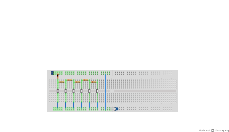
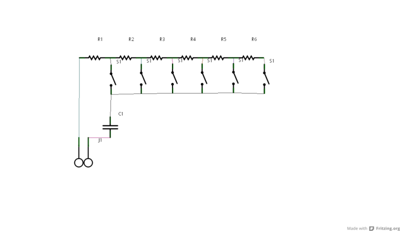
Back in the 90's the Parralax stamp used 1 pin for 8 switches.
Bad fritzing but will give you an idea.
In this example (cant find single pin of gnd plane )
The resistors are connected to an analoge in pin and the capacitor end is connected to gnd (or however the netduino handles it)
The whole thing reads as a potentiometer so is simple to work.
Going by what I have lurned so far you may be able to drop the cap.
I hope this helps with your button issue.
Thats an interesting idea, thank you.
Ill keep this in mind, wouldn't this idea how ever require some slight pre-programming of the values per switch and also, if i press multiple switches at once, would this not cause an issue?
Thats an interesting idea, thank you.
Ill keep this in mind, wouldn't this idea how ever require some slight pre-programming of the values per switch and also, if i press multiple switches at once, would this not cause an issue?
I would assume so, Maybe some sort of array would be required, yes multiple presses would be an issue as this circuit being used without care could create false reading.
I'm still learning electronics after a 7 year leave and this is a 13 year old circuit! (OMG thats old!)
Fyi All the resistors are supposed to be the same value!
The code I have would (in thory) use a centralised "shared" SPI bus (a static property of the main program, initialized on startup). Could i not modify it to work with the "shared bus"?
Yes you can, or use a modified version which saves you some time, your choice
Another benefit of the class I wrote is that it can combine multiple 74HC595s daisychained with only one latch pin, enabling more outputs without occupying more pins on the netduino. I even got multiple LCD's connected with one latch pin:
Thats an interesting idea, thank you.
Ill keep this in mind, wouldn't this idea how ever require some slight pre-programming of the values per switch and also, if i press multiple switches at once, would this not cause an issue?
Actually, you can do that as well. But it's much harder to detect when multiple buttons are pressed. I would not prefer that way, personally.
I want to have a menu system accessible by buttons on my project. The display will be a 20x4 LCD Display and there will be 6 buttons as follows:
UP
DOWN
LEFT
RIGHT
OK
CANCEL
Why not buy an LCD which has all that available? I can't recall the LCD I have at the house, but its 20x4 (IIRC), up,down,left,right,ok,cancel and fits in a 5 1/4" drive bay. I bought it quite a few years ago, so I don't recall the brand off the top of my head, but they had a serial and LCD version. But I will look tonight.
The Matrix Orbital 212 is US $78 which has 7 buttons, 20x4 and fits in a 5.25" drive bay.
Actually, you can do that as well. But it's much harder to detect when multiple buttons are pressed. I would not prefer that way, personally.
Just had a re read of the notes and rechecked the diagrams, the circuit will only read the lowest button pressed ( in the event of multipress) due to the way electricity flows.
Just FYI, the analog circuit above (switches and resistors) won't work at all.
Even corrected, it has some limitations respect the HC595 version. For example, by pressing two buttons together it's hard to detect for the Netduino. Using the 595 is trivial.
A vote up for the Stefan's tip!
Cheers
Biggest fault of Netduino? It runs by electricity.
The resistor network works pretty well. I have a DF Robot shield which uses this.
That shield has Up,Dn,Left,Right,Select and Reset(The ultimate cancel?)
One thing that may be a limitation is that it needs to be polled.
You can't trigger an interrupt from an analog input pin. but you could use 2 pins, one as an interrupt port and the other as an analog input and feed the signal into both.
for a digital IO pin voltages over 2.0v are a logic high so arrange the reseistor network so that a voltage of 0v for no keys pressed and voltages of 2.0 - 3.3v for the 6 keys. That's 260mv spacing.
I haven't done the math but that sound like plenty of discrimination.
The digital pin would be used to trigger an interrupt on a rising edge.
Multiple keys being pressed simultaneously can be detected as long as the first key has a lower voltage than the second key.
Usually when you use multiple keys simultaneously you hold one and press the second.
I think that you should be able to implement more than 6 keys with interrupt on keypress and using only 2 pins.
@Mike P: could you post the actual schematic?
The above Fritzing/schematic absolutely can't work.
EDIT: I have a peek at the Parallax technique for reading the button pressed, but it is not simple as the Netduino can do.
You should set the pin as an Output (high), so that the capacitor will charge. After a *precise* delay, the Output should switched as AnalogPort, and read the value.
I confirm that the circuit can't be applied to the Netduino.
If you don't like the Stefan's idea, you might use a resistor network as well, but connecting the resistors differently.
Biggest fault of Netduino? It runs by electricity.
Now I've got to put my money where my mouth is!
This should work but untested
6key IF_bb.png42.54KB61 downloads6key IF_schem.png47.5KB62 downloads
I tried to put a table in below but the TABs get stripped out so it's in CSV form instead.
The table below gives the resistor values,
The total resistance when the button is pressed,
The voltage on the analog input,
The ADC reading,
The difference between the ADC value for this button and the next one up,
and the suggested cut-off value to use when deciding which button has been pressed
I even managed to keep to common value resistors and get very even separation between the voltages.
Vcc=3300mV
Button,Resistor,Total R,mV,ADC,delta,cutoff
Cancel,1500,1500,3300,1024,,986
Right,120,1620,3056,948,76,908
Left,150,1770,2797,867,81,827
Down,180,1950,2538,787,80,747
Up,220,2170,2281,707,80,668
Select,270,2440,2029,629,78,315
None,,,0,0,629,
In the schematic the second analog input pin would actually be used as a digital interrupt pin and could be on any of the GPIO pins. Its not necessary if you don't mind polling the analog input continuously.


 .
.

 )
)


