The Netduino forums have been replaced by new forums at community.wildernesslabs.co.
This site has been preserved for archival purposes only
and the ability to make new accounts or posts has been turned off.
Would love to get some feedback on this, but please, keep in mind I'm a newb
I think it should get some resistors, although it works.
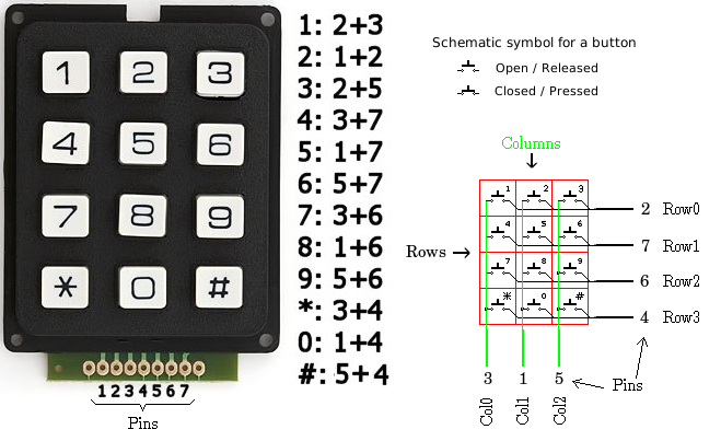
The working of the keypad is best explained as in this image I think:
Every row and column has a pin. They could be numbered like this:
Pin 1: Column 1
Pin 2: Column 2
Pin 3: Column 3
Pin 4: Row 1
Pin 5: Row 2
Pin 6: Row 3
Pin 7: Row 4
But keep in mind, this can be different on your keypad. Always follow the lines. Here's a picture of the inside of my keypad.
If I press button 8, it's row 3 and column 2. At that moment, pin 6 and 2 are connected to each other. So I can scan if key 8 is pressed by putting a signal on pin 6 and read it on pin 2. If the signal exists, button 8 is pressed.
So far the theory on the keypad. I connected it to the Netduino like this:
With the MatrixKeyPad-class I wrote, I actually get the pressed button correctly, so it works.
First, I reassigned the rows and cols pins to match the Sparkfun model as following:
// Row pins. The keypad exists out of 4 rows.
Cpu.Pin[] RowPins = { Pins.GPIO_PIN_D2, Pins.GPIO_PIN_D7, Pins.GPIO_PIN_D6, Pins.GPIO_PIN_D4 };
// Col pins. The keypad exists out of 3 columns.
Cpu.Pin[] ColPins = { Pins.GPIO_PIN_D3, Pins.GPIO_PIN_D1, Pins.GPIO_PIN_D5 };
Second, I matched the values I got from the event handler with the corresponding key:
        public enum Sparkfun12ButtonsKeypad : uint
        {
            One = 0x00, // Button 1 on the keypad
            Two = 0x01, // Button 2 on the keypad
            Three = 0x02, // Button 3 on the keypad
            Four = 0x03, // Button 4 on the keypad
            Five = 0x04, // Button 5 on the keypad
            Six = 0x05, // Button 6 on the keypad
            Seven = 0x06, // Button 7 on the keypad
            Eight = 0x07, // Button 8 on the keypad
            Nine = 0x08, // Button 9 on the keypad
            Star = 0x09, // Button * on the keypad
            Zero = 0x0A, // Button 0 on the keypad
            Hash = 0x0B, // Button # on the keypad
        };

        // Too bad that .NET MF don't have Enum.GetName() Method ):
        public static string GetKeyName(uint value)
        {
            Sparkfun12ButtonsKeypad pressedKey = (Sparkfun12ButtonsKeypad)value;
            switch (pressedKey)
            {
                case Sparkfun12ButtonsKeypad.One:
                    return "1";
                case Sparkfun12ButtonsKeypad.Two:
                    return "2";
                case Sparkfun12ButtonsKeypad.Three:
                    return "3";
                case Sparkfun12ButtonsKeypad.Four:
                    return "4";
                case Sparkfun12ButtonsKeypad.Five:
                    return "5";
                case Sparkfun12ButtonsKeypad.Six:
                    return "6";
                case Sparkfun12ButtonsKeypad.Seven:
                    return "7";
                case Sparkfun12ButtonsKeypad.Eight:
                    return "8";
                case Sparkfun12ButtonsKeypad.Nine:
                    return "9";
                case Sparkfun12ButtonsKeypad.Star:
                    return "*";
                case Sparkfun12ButtonsKeypad.Zero:
                    return "0";
                case Sparkfun12ButtonsKeypad.Hash:
                    return "#";
                default:
                    throw new System.ArgumentOutOfRangeException("value", "There is no such key.");
            }
        }

        static void kb_OnKeyUp(uint data1, uint data2, DateTime time)
        {
            Debug.Print("Key released: " + GetKeyName(data1));
        }

        static void kb_OnKeyDown(uint data1, uint data2, DateTime time)
        {
            Debug.Print("Key pressed: " + GetKeyName(data1));
        }
That's working right, except when you are pressing more than a button simultaneously.
If that is not a problem, the circuit is almost okay.
The only suggestion I'd like to tell you, is to configure the outputs as open-collector with pullups, instead of the standard push-pull. Supposing the outputs are the rows and the inputs are the columns. When you scan the row #1, you may drive that output to "high" (+3.3V), so the other rows are to "low" (0.0V). If a (dumb) user presses buttons "3" and "6" together, then it shorts the outputs and it will flow an high current through the output pins. Maybe it's not dangerous, but it may be better to prevent it, I think.
If you configure the output as open-collector with pull-ups resistor, there's no any damage, nor high currents. Probably you may also able to detect "collisions" like the example via software. http://en.wikipedia..../Open_collector
I'm using Sparkfun 12 Buttons Keypad and I had to make some changes to get it to work.
First, I reassigned the rows and cols pins to match the Sparkfun model as following:
I indeed noticed that not all keypads are the same. I checked mine to see how the pins were connected to the rows and columns, and that is still the best method I think. Also, there are 3x3 keypads in existence as well. My class can work with any amount of rows and columns, the basic principle remains the same. It would, for example, also work with this 27-button keypad: http://www.sparkfun.com/products/8871
That's working right, except when you are pressing more than a button simultaneously.
If that is not a problem, the circuit is almost okay.
As far as my knowledge goes, it's impossible to detect multiple keypresses in many occasions. For example when I press three buttons: 1, 2, and 5, it will also detect that 4 is pressed as well.
The only suggestion I'd like to tell you, is to configure the outputs as open-collector with pullups, instead of the standard push-pull.
Hmm, there is something to learn
I'm not that good with electronics and all I do is done by schematics I found elsewhere.
But if I understand this correctly, when two buttons in different columns and the same row are pressed, there will be two outputports parallel connected to each other which will increase the amperes that are going out right?
If that's what you mean, and I understand the working correctly, I got only one output port active at all time, so I don't think this will do any harm. If I'm mistaken, please tell so though. Don't want to brick any netduino
But if I understand this correctly, when two buttons in different columns and the same row are pressed, there will be two outputports parallel connected to each other which will increase the amperes that are going out right?
Yes and no.
It is true that two output connected in parallel double the available current, but *ONLY* if both they are at the same output voltage!...That is logic high (=3.3V), i.e. "true" on the software.
If the outputs are connected to different levels, then the current sourcing from the "high"-one flows directly to the "low"-one (often called "sink"). That's NO good!
Consider a push-pull output as two switches sharing a common point (the output), then one is connected to +3.3V and the other to ground (0.0V). The CPU logic grants that ONLY one of these switches would be closed at once, otherwise will be a short. That's basically what I mean.
Modern logics are designed with mosfets as switches and usually are well protected against shorts...but they are "protected" to avoid imprecations from the users!
The "open-collection" circuit uses only one switch to the ground, then having a resistor that "pull-ups" the voltage when the switch is off. Even when the switch is closed, that resistor is large enough to limiting the current to -let's say- 100's of microamps. In this case, there's no problem of overcurrents, blowing or whatever else on the circuit.
NOTE: even 100 microamperes seems a leak current, it's quite large to drive an input of a CMOS logic. (In the sense, 1 micro ampere is still 1.6E+13 electrons flowing every second!)
Cheers
Mario
Biggest fault of Netduino? It runs by electricity.
So it's not the problem of two combined outputs to one input, but more that two outputs linked to each other will compensate each other so current will go in the 0V output. Right?
If that's the case, it could also be solved by adding diodes between the keypad column-pins and netduino I think?
I'm trying to understand the problem exactly and find a very simple solution.
Thanks in advance for your patience
The problem is not the compensation, but the excessive current flowing through the "switches" of the outputs embedded in the CPU.
Anyway you do not need any diode for the Netduino, because there is a much simpler way:
public static TristatePort _row0 = new TristatePort(
            Pins.GPIO_PIN_D0,
            false,                 //output state
            false,                 //filter (don't mind)
            Port.ResistorMode.PullUp);
A "TristatePort" is a port acting both for input and for output.
You may do as follows:
public static void SetActiveRow(int r)
{
  _row0.Active = r == 0;
  _row1.Active = r == 1;
  _row2.Active = r == 2;
  _row3.Active = r == 3;
}
Common habits is to detect the low-level voltage (i.e. "false") instead of the "high".
Mario
Biggest fault of Netduino? It runs by electricity.
private static TristatePort[] _rows = new []
{
  new TristatePort(
            Pins.GPIO_PIN_D0,
            false,                 //output state
            false,                 //filter (don't mind)
            Port.ResistorMode.PullUp),
  new TristatePort(
            Pins.GPIO_PIN_D1,
            false,                 //output state
            false,                 //filter (don't mind)
            Port.ResistorMode.PullUp),
    // ...
};

public static void SetActiveRow(int r)
{
  for (int i=0; i<_rows.Length; i++)
    _rows[i].Active = false;

  _rows[r].Active = true;
}
So there's no collision (glitch), even when you set activity from row 2 to row 1, for example. In the previous post you may have a small fraction of time where are both active row #2 and row #1.
What a funny day!
Mario
Biggest fault of Netduino? It runs by electricity.
Thanks for the help Mario, you've been very helpful!
Tonight I will make some modifications to my code, currently I'm at work and hard to debug without Netduino
You can do it even better avoiding the scanning timer and using as inputs the InterruptPorts. An InterruptPort gives you an event upon a change on the pin. Since that event is fired directly from an interrupt of the CPU, the result is greatly more performing and less resource wasting. http://msdn.microsof...y/ee434402.aspx
Good luck.
Mario
Biggest fault of Netduino? It runs by electricity.
Hi Mario,
I thought about that, but the problem is, I don't get input without sending output. Therefor I need to scan every port after setting another high. I can't see how this could be done with an InterruptPort.
I did a 4x4 keypad decoder as well. In my case I used a 8574 chip and the I2C bus, but the basic idea is the same. You may get some ideas from the code I wrote for that, see http://www.fezzer.co...-port-extender/
Stefan, klotz is right.
He is using an I/O expander I2C-Bus, but it is not important.
You may use the interrupt only to detect that something has been pressed. Once in the interrupt routine, you can scan row and columns to detect which button is pressed.
Mario
Biggest fault of Netduino? It runs by electricity.
Thanks for the feedback. I will look into it this weekend. But doesn't that method has the problem sending power to an interrupt port when two buttons are pressed at the same time?
The ammount of current being dumped into the interrupt is not a issue, what you should be worried about is the ammount of current being drawn on the outputport driving the columns. Even in that case, the ammount of current is negligable. Worstcase for any one driver would be 4 keys. If you are seriously worried about it you can mitigate the problem by driving the 4 rows and have the Columns as the interrupts, in that case the worse case would be 3 keys.
There's no problem at all, in any case.
If you driver all the outputs to a logic low level (i.e. 0.0V), then you may even short them because they share the same voltage. The problem could arise when they output *different* voltages.
Cheers
Mario
Biggest fault of Netduino? It runs by electricity.
Thanks both for the feedback, very useful.
I wrote a new version, available at http://nederland.lig...0313_keypad.zip
Here I used interruptports. The public events and functions still remain the same but the code behind that is totally different


