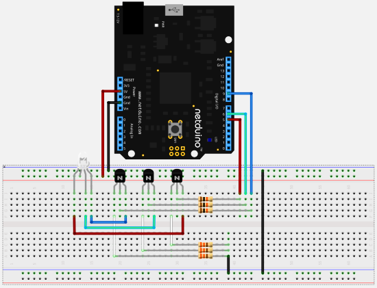
I have got some of the RGB Leds with common cathode, that I would like to experiment with:
 rgb_led_cathode.png 50.46KB
0 downloads
I went through some of the postings on the forum (like http://forums.netdui...ed-pwm-sample/)and made it work with 500 ohm resistors to be on the safe side (as far as I undestand).
It seemed to me that setting the same values for different colors do not produce the same brightness. If I look at the specifications of the RGB Led from Sparkfun, it looks like there are different voltages for each color, so it would probably require a different resistor for each color.
I found that CW2 wrote in the posting that for the best result, it is better to add transistors, and Embedded Lab post shows using 1 rgb led, 3 transistors and 6 resistors (this is a "common Anode" version of RGB led):

For the sake of trying to make it work "better", I would like to know how to do the calculation of what kid of transistors and what kind of resistors (when both are involved) I need in a little bit more details. Could someone help me wit that?
Thanks


